sales@bonporaparts.com
0086-10-64988621
English
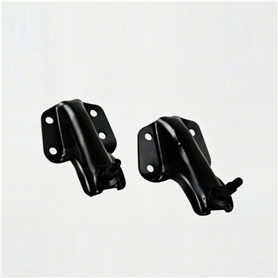
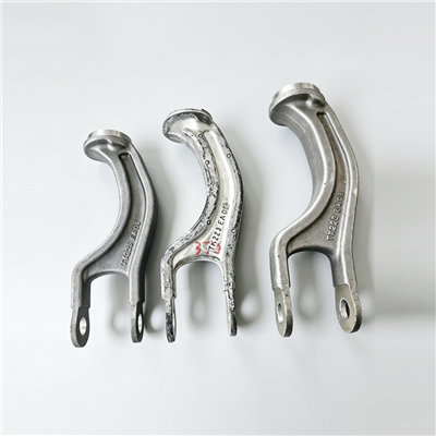
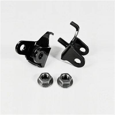
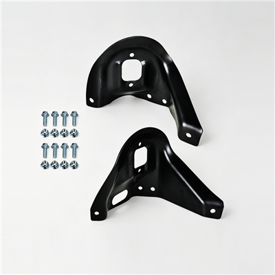
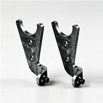
Brackets are the quiet part of a vehicle or machine structure. A bracket installed on the equipment body, frame, or panel is used to secure, support, or suspend other components. It provides mounting interfaces for attaching accessories such as pipelines, sensors, and motors, enhances structural rigidity to resist vibration and impact, and simplifies assembly processes through modular design. Bonpora supplies brackets in carbon steel, stainless steel, aluminium alloy, and zinc alloy die-casting, and accepts reverse engineering based on customer 3D models or physical samples to optimise structural strength and lightweight design, with rapid prototyping supported.
Because a bracket holds load without moving, it is often the last item on the inspection list. When it fails, the consequence is rarely a broken bracket alone. A cracked sensor mount takes a pipe with it, a deformed suspension bracket changes the geometry of an entire corner, and a loosened panel bracket lets a heat shield rattle against a fuel line. This guide is written for maintenance engineers, fleet workshops and trade buyers who need to recognise bracket failure early, decide between repair and replacement, and specify the next batch so the same failure does not return.
A bracket does not rotate or slide, so buyers reasonably expect it to last the life of the machine. In service the bracket is loaded in a way that a catalogue photograph never shows. Three conditions combine. First, the bracket is usually a cantilever: the load hangs off the end of an arm, so a modest force at the attachment point becomes a large bending moment at the root. Second, that load is not steady but repeated, arriving as vibration from the engine, the road, the pump or the process equipment. Third, the part is clamped by fasteners that lose preload over time. Repeated load with declining clamp force is the classic recipe for fatigue cracking, hole elongation and loosening.
The practical conclusion is that bracket health cannot be judged by looking at the bracket alone. Corrosion at the mating face, a stretched bolt, a hardened washer that has lost its spring, or a hose that has been pulled tight against the arm will all show up first as a bracket problem. Diagnose the load path, then decide what to replace.
Most bracket returns fall into one of six patterns. Naming the pattern correctly is what stops a workshop from replacing the same part three times.
For fabricated carbon steel and stainless steel brackets, the weld toe is the geometric stress raiser. Cracks start as a fine line along the toe, often under the paint and invisible until the coating flakes. They grow perpendicular to the principal stress, so on a cantilever arm the crack usually runs across the flange or down the web. A crack that has travelled more than a third of the section width is a replacement, not a repair.
Elastic deflection springs back; permanent set does not. Once a bracket has been overloaded, the hole centres and the mounting angle change, and the attached component is no longer in its designed position. Bent arms are common after a kerb strike, a lifting incident or a hydraulic shock. Measure hole-to-hole distance and compare it with the drawing rather than judging by eye.
Road salt, wash-down chemicals and condensation collect in the pocket between the bracket and the panel, where air movement is poor and coating coverage is weakest. Where a steel bracket is bolted to an aluminium housing, or a stainless fastener sits in an aluminium bracket, moisture plus a potential difference creates a small galvanic cell. Attack concentrates around the fastener and along the joint line, thinning the section exactly where the load is highest.
When clamp load falls, the joint starts to slip under vibration. The bolt shank then works against the hole wall and converts a round hole into a slot. Elongation is a warning that the joint was under-torqued, that the wrong washer was used, or that the bracket was never designed with a positive location feature such as a shoulder or a dowel.
Micro-movement of a few micrometres between two clamped faces removes the oxide layer and produces fine reddish-brown debris. In stainless steel joints the same mechanism can cold-weld the faces together, so the bracket has to be cut off. Fretting marks are a reliable sign that the clamp load has been lost even if the fasteners still look tight.
Zinc alloy die-castings and thin aluminium extrusions save weight but offer limited thread depth. Repeated assembly, over-torque or a thread-forming screw used one time too many pulls the thread out of the casting. The same parts crush or crack at the bolt hole edge. Where a bracket is likely to be disassembled more than twice, specify a steel insert, a through-bolt with a nut, or a thicker boss.
| Failure mode | Typical appearance | Root cause | Field action |
|---|---|---|---|
| Fatigue crack | Fine line at weld toe or hole edge, coating flaking | Repeated bending, stress raiser, lost preload | Replace; verify torque and support of attached parts |
| Permanent deformation | Bent arm, changed hole centres, gap at mounting face | Overload, shock load, undersized section | Replace; check the attached component for damage |
| Corrosion and galvanic attack | Rust pitting in pockets, white or grey powder at joint | Trapped moisture, dissimilar metals, coating damage | Replace; add barrier washer or change material pair |
| Loosening and hole elongation | Slotted holes, polished witness marks around bolt head | Low preload, missing locking feature, vibration | Replace bracket; specify positive location and correct torque |
| Fretting wear | Red-brown debris, seized faces, black oxide smear | Micro-slip, clamp load below design value | Replace; add hardened washer and review clamp load |
| Thread stripping | Torn thread in casting, cracked hole edge | Repeated assembly, over-torque, thin boss | Replace; use insert or through-bolt design |
Drivers and operators usually report a symptom rather than a failure. The table below links the common complaints to the bracket condition that usually explains them and to the check that confirms it.
| Reported symptom | Probable cause | Confirming check |
|---|---|---|
| Rattle or knock over rough ground | Loose fastener or fretting at the clamped face | Witness marks around bolt head, debris between faces; re-torque test |
| Component sits off centre or out of alignment | Permanent set in the bracket arm | Hole centre distance and mounting angle against drawing |
| Crack visible near a weld | Fatigue at the weld toe | Dye penetrant or magnetic particle inspection along the toe |
| Pipe or harness contact or chafing | Bracket deflection under load, hose pulled tight | Measure clearance at static load and with the machine running |
| Fastener keeps coming loose after re-torque | Hole elongation or loss of joint stiffness | Hole roundness gauge, check washer condition and thread depth |
| White or grey powder at the joint | Galvanic corrosion of aluminium or zinc part | Identify the material pair and the source of standing moisture |
Replacing a bracket without understanding the cause simply resets the clock. Five short steps take less than an hour and usually identify both the failed part and the reason it failed.
Write down what the operator hears or sees, when it appears, and how long the part has been in service. Note mileage or running hours, typical load, and whether the machine works in salt, dust or wash-down conditions. A bracket that lasted 200,000 km in a dry climate and one that lasted 30,000 km on salted roads are telling different stories.
Trace the force from the attached component back into the structure. Check for a stiff hose that has been pulled tight, a support that was removed during an earlier repair, or a second bracket that is already cracked and is now sharing load unevenly. More than one bracket failure in the same area usually means the load path changed, not that the bracket is weak.
Use callipers for hole centre distance, a square or angle gauge for the mounting face, and a straight edge for arm flatness. Compare with the drawing values and record the deviation. Nominal dimensions on the drawing are the acceptance basis; a bracket that has moved more than the drawing tolerance should not go back on the machine.
Remove the fasteners and look at the threads, the washer, the hole walls and the mating face. Stretched bolts, collapsed spring washers, polished slip marks and fretting debris all point to a joint that lost clamp load. If the hole is elongated, the correct action is a new bracket plus a design change such as a dowel, a shoulder bolt or a wider clamping washer from the washer range.
Use section loss, crack length and distortion as the deciding variables. The rule table below reflects what most OEM service literature accepts.
| Condition found | Crack or distortion | Correct action |
|---|---|---|
| Coating damage only, no section loss | None | Clean and recoat; keep part in service |
| Surface corrosion, section loss under 10 percent | None | Evaluate for reuse; improve drainage and coating |
| Crack under one third of section width at a weld toe | Local | Replace; repair welding is not recommended for fatigue cracks |
| Crack beyond one third of section width, or multiple cracks | Advanced | Replace and review the joint design |
| Permanent set beyond drawing tolerance | Permanent | Replace; do not straighten and reuse |
| Elongated holes or stripped threads | Wear | Replace; add positive location or thread insert |
Bracket failures repeat in fleets because the evidence is thrown away with the part. Recording a small, fixed set of fields turns a repair into data. Keep the record with the unit number and the date so that a pattern becomes visible after a few months.
Record the bracket part number and the material marking, the position on the machine, the running hours or mileage, the failure mode from the six above, the measured deviation from the drawing, the condition of fastener and interface, the probable root cause, the action taken, and photographs of the failed area before cleaning. When the same position fails again, the earlier sheet usually shows that the root cause was never corrected. This is also the evidence a supplier needs if a batch is being investigated, which is why trade buyers should insist on the same fields from their service partners.
Welding a fatigue crack back together rarely lasts, because the repair leaves the original stress raiser in place and adds heat-affected material around it. For low-stress, non-structural brackets and for cast or die-cast parts, repair is generally not acceptable at all. The practical rule is that any bracket carrying the weight of another component, or locating a safety-related item, is replaced once a crack or permanent set is found.
Redesign is worth considering when the same position has failed more than once. Common changes that solve real problems include increasing the section at the root of the arm, adding a gusset or a return flange, moving the fastener pattern so that the bolts share load rather than acting in line, replacing a single thick bracket with two lighter brackets that split the load, and changing the material from a die-casting to a formed steel part where repeated disassembly is expected.
Corrosion control is mostly about water and contact. Provide a drain path so that water cannot stand in the pocket behind the bracket. Apply coating to all faces before assembly, and repair coating damage at fastener seats after installation. Where dissimilar metals must be joined, break the electrical path with a barrier washer or an insulating sleeve from the sleeve range, and keep the less noble material as the larger area if it cannot be avoided.
Assembly discipline matters as much as design. Clean the mating faces, remove burrs, use the specified torque with a calibrated wrench, and check torque again after the first running period. If a joint must survive many disassembly cycles, specify a thread insert or a through-bolt rather than relying on a thread cut directly into a light alloy. For custom geometry, reverse engineering from a sample or a 3D model is a normal part of the process described in the custom parts service.
Buyers hold the last lever against repeat failures: the specification. Three items make the biggest difference. First, state the material with a standard designation instead of a generic description, so that a carbon steel bracket and a stainless steel bracket cannot be substituted for one another. Second, state the surface treatment and the coating thickness range, since the pocket area of a bracket is the first place corrosion starts. Third, state the inspection evidence expected on the batch, such as material certificates, dimensional report, coating thickness readings and, where the part is structural, a load or fatigue test report.
It is also worth agreeing the acceptance basis for holes and threads. A drawing that gives hole diameter and position tolerance, plus a note on the thread depth and the minimum boss thickness, removes most of the arguments that follow a failure in the field. The bracket range shows the standard configurations available in carbon steel, stainless steel, aluminium alloy and zinc alloy die-casting, and the selection and specification guide covers the material and stiffness decisions in more detail.
For a non-structural bracket that only holds a cover, a repair weld may be acceptable if the material is weldable and the crack is fully removed. For any bracket that supports another component, and for all cast and die-cast parts, replacement is the accepted practice because the stress raiser and the heat-affected zone remain.
Look at the hole and the clamped faces. Fretting debris, polished slip marks and elongated holes indicate that clamp load was lost, so the joint design or the installation torque is the cause. A clean hole with a crack running away from it points to fatigue in the bracket itself.
Straightening a formed or fabricated bracket that has taken a permanent set is not recommended. The material at the bend has already yielded, the hole positions rarely return to drawing tolerance, and the cold work leaves reduced ductility at exactly the point where the next load peak will arrive.
Material grade, section thickness with tolerance, hole diameter and position tolerance, thread size and minimum depth, surface treatment with coating thickness range, and the inspection documents required per batch. Adding the expected installation torque and the number of expected disassembly cycles helps the factory choose between a welded, bolted or cast construction.
Bonpora supplies brackets for equipment bodies, frames and panels, handles reverse engineering from customer drawings, 3D models or physical samples, and supports rapid prototyping when a design change needs to be proved before tooling. Send the failed part details, the duty condition and the required batch size through the contact page, or start from the product index to see the adjacent component families.