sales@bonporaparts.com
0086-10-64988621
English
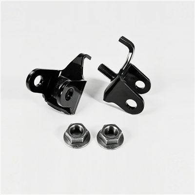
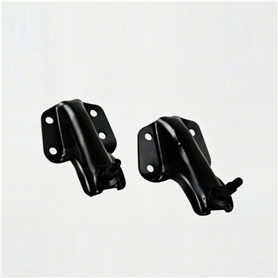
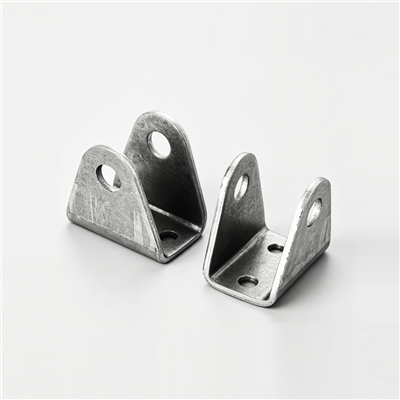
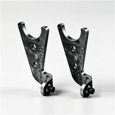
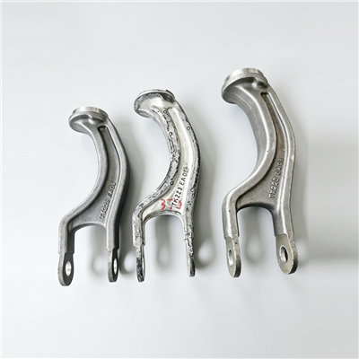
A bracket installed on the equipment body, frame, or panel is used to secure, support, or suspend other components. Its working life is decided less by the catalogue drawing than by the hour it spends being fitted. The same bracket that lasts a decade when it is installed onto a flat, clean, correctly torqued face can crack within a season when it is pulled down onto a burr, clamped with the wrong washer, or forced into alignment with the fasteners. This guide sets out a repeatable installation procedure for carbon steel, stainless steel, aluminium alloy and zinc alloy die-cast brackets, and explains the points where workshops most often go wrong.
Bonpora supplies brackets for equipment bodies, frames and panels, and also works from customer 3D models or physical samples to optimise structural strength and lightweight design, with rapid prototyping available for design changes. Whatever the source of the part, the assembly rules are the same.
Installation begins with three questions about the mounting face. Is it flat within the tolerance the joint needs. Is it clean enough for metal-to-metal contact. And does the hole pattern allow the fasteners to clamp the bracket without distorting it. A bracket that spans a weld bead, a paint ridge or a casting seam will bend as the bolts are tightened, and a bent bracket is a pre-loaded bracket: it has already used part of its strength budget before any service load arrives.
Check also what the bracket is being asked to carry. The mounted component should sit in its designed position with the fasteners only just snug; if it has to be levered into place, either the bracket, the mounting face or the attached part is wrong. Forcing alignment with a bolt is the single most common cause of stripped threads in light alloy fittings and cracked welds in fabricated steel brackets.
Remove rust, scale, old sealant, paint runs and swarf. Pay particular attention to the area around each bolt hole, since that is where the clamp load is transferred. On a repaired machine, remove any weld spatter that would sit under the bracket. A face that is clean and dry will hold torque far more consistently than a face covered with oily residue.
Sheared or punched holes carry a burr on one side. That burr distributes clamp load over a ring of almost nothing and loosens as it is crushed. Deburr both sides, then run a thread chaser through tapped holes to remove paint and old locking compound. Do not use a tap to remove a thread insert; if the thread is damaged, fit a replacement insert rather than making the hole larger.
Match the bolt grade to the drawing and check the length so that the thread does not bottom in a blind hole. Flat washers spread load and protect the coating; hardened washers are used where the clamp load is high. Spring or wedge-locking washers are added when the joint sees vibration. Where a steel fastener clamps a light alloy bracket, an insulating or barrier washer from the washer range also interrupts the galvanic path.
Not every bracket is bolted. The choice of joint type is usually made at design stage, but the installer needs to know what each method demands.
| Method | Typical use | Installation requirement | Watch point |
|---|---|---|---|
| Bolt and nut | Serviceable joints, steel and alloy brackets | Torque to drawing, washer under head and nut | Thread must not bottom in blind hole |
| Bolt into tapped boss | Die-cast zinc or aluminium housings | Clean thread, correct torque, no reuse of self-tapping screw | Low thread depth, easy to strip |
| Through-bolt with sleeve | Thin panels, hollow sections, crush risk | Sleeve length sets the crush height | Sleeve must bottom on both faces |
| Rivnut or thread insert | Sheet metal panels, repeated disassembly | Correct grip range, square setting | Pull-out if panel is too thin |
| Welded bracket | Frames and structural brackets | Cleaned surface, controlled heat input, sequence to limit distortion | Distortion and coating damage |
| Clamped or bolted with shim | Frames with uneven faces, alignment adjustment | Shim stack on full face, not under one corner | Shims crush and joint loosens |
Brackets with four or more fasteners should be tightened in a crossing pattern in two stages: first to about half the final torque, then to the full value. This spreads the clamp load evenly and reduces the risk of trapping a gap at one corner. Where the drawing gives a torque range, work to the mid-point rather than the maximum, especially on alloy threads.
Torque figures assume clean, lightly lubricated threads. A dry, corroded thread reaches the same torque with far less clamp load, which is one reason a joint that measured correctly on the wrench can still loosen in service. Use a calibrated wrench, and re-check torque after the first operating period on any bracket that carries a vibrating component.
| Fastener size | Typical dry torque for class 8.8 steel | Typical torque into light alloy boss | Practical note |
|---|---|---|---|
| M6 | 8 to 10 Nm | 4 to 6 Nm | Use washer under head and nut |
| M8 | 20 to 25 Nm | 10 to 14 Nm | Check boss height before final torque |
| M10 | 40 to 50 Nm | 18 to 24 Nm | Hardened washer recommended |
| M12 | 70 to 85 Nm | Not recommended without insert | Prefer through-bolt on alloy |
These values are typical field guidance only. The drawing or the machine manual always takes precedence, and any bracket that locates a safety-related component should be torqued to the published value with a calibrated instrument.
Once the bracket is clamped, confirm the position of whatever it carries. Measure the gap between the mounted component and the nearest fixed part, and check that no hose, harness or pipe is touching a bracket edge or a fastener head. Clearance problems rarely show up when the machine is stationary; where possible, check again with the machine running at normal speed and load so that vibration travel is included.
Where the design intends a sliding or rotating interface, check the fit against the drawing. A bracket that clamps a tube or a shaft should grip without deforming it, and a bracket that carries a rotating part should leave the specified running clearance. Where a protective sleeve or bushing sits in the assembly, see the sleeve range for guidance on interference and clearance fits.
Coating is the first casualty of installation. Touch up scratches and any damage around the fastener seats before the machine goes back to work, using the same coating system as the original. Where a bracket sits in a pocket that collects water, confirm that the drain path is clear and not blocked by a larger washer or a blob of sealant. On dissimilar metal joints, check that the barrier washer or insulating sleeve is present and correctly seated, because a missing insulator turns a mounting point into a small corrosion cell that shows up two seasons later.
Thread locking compound should be used where the drawing specifies it and not as a substitute for correct torque. Medium-strength compound suits brackets that may be removed for service; high-strength grades make future removal difficult and can shear a small bolt on disassembly.
| Installation error | Immediate sign | Later symptom |
|---|---|---|
| Bracket forced to align with a bolt | Bolt feels tight early, visible pre-load bow | Crack at weld toe or hole edge, hole elongation |
| Not deburring punched holes | Torque drops after a short time | Fastener loosening, fretting debris under bracket |
| Wrong washer omitted | Bolt head marks the coating | Coating breakdown, corrosion under the head, loosening |
| Over-torque into die-cast boss | Thread feels soft or spinning | Stripped thread, bracket movement |
| Shim used on one corner only | Gap closes unevenly | Shim crush, loss of clamp load, bracket distortion |
| Coating damage left bare | Bright metal visible at edges | Localised corrosion and section loss around the joint |
| No re-torque after first run | Nothing noticed | Loosening after weeks of vibration, rattle or knock |
A short, fixed check list is the cheapest quality control available to a workshop. Confirm that all fasteners are present and torqued to the specified value with a calibrated tool. Check that the bracket sits flat with no visible gap at any corner, using a feeler gauge if the drawing calls for one. Verify the position and clearance of the mounted component, including hose and harness routing. Confirm that the coating has been repaired at every fastener seat and scratch. Record the unit number, the bracket part number, the date and the torque values used. If the part is a replacement for an earlier failure, compare the new installation against the earlier record to confirm that the root cause has actually changed, as described in the failure analysis guide.
Some repeat failures cannot be fixed on the shop floor. If two brackets at the same position have loosened or cracked despite correct torque, the joint needs a design change rather than another replacement part. Typical changes that help are a thicker boss for the fastener, a dowel or shoulder to locate the bracket positively instead of relying on friction, a larger hardened washer to spread load, or a change of material and forming route. The bracket range covers carbon steel, stainless steel, aluminium alloy and zinc alloy die-cast options, and the selection and specification guide explains how to choose between them.
For brackets that are not held in a catalogue, reverse engineering from a sample or a 3D model is routine. Send the failed part, the mounting face condition and the duty condition, and the design can be adjusted for strength or weight before the next batch is produced. Rapid prototyping is available where a change needs to be proved on the machine before tooling. Start from the custom parts service or the metal components range.
Use it where the drawing specifies it. On a joint that is correctly torqued and has a hardened washer or a locking feature, compound is normally unnecessary. It should never be used to compensate for a low clamp load or a damaged thread.
Re-check after the first operating period, which for a vehicle or a vibrating machine is usually a few hundred kilometres or the first shift of running. Record the result and check again at the next scheduled service, since a joint that holds tension twice is unlikely to move.
Only if the threads are undamaged, the bolt has not been stretched and no locking coating has failed. Bolts that have been loosening in service are best replaced, because their preload history is already compromised. Torque-to-yield fasteners are single use.
Follow the drawing, and stay in the lower half of any published range when threading into aluminium. Aluminium has a lower stripping strength than steel, so the thread, not the bolt, is the limiting item. Where the drawing allows, a through-bolt with a nut and washer is a safer solution.
Send the bracket drawing or sample, the mounting face material and thickness, the load the bracket carries and the number of expected service removals. The factory will confirm the material, the fastener arrangement and the surface treatment before production, and can produce a prototype first where the application is critical. Reach the team through the contact page.