sales@bonporaparts.com
0086-10-64988621
English
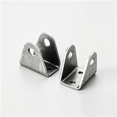
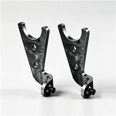
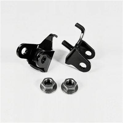
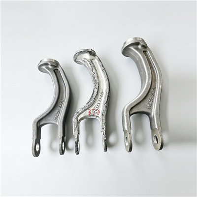
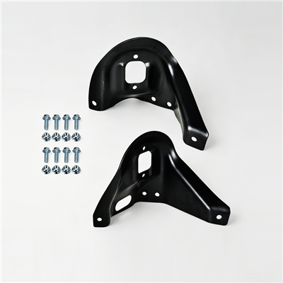
A bracket is installed on the equipment body, frame or panel, and is used to secure, support or suspend other components. It provides the mounting interfaces for attaching accessories such as pipelines, sensors and motors, it enhances structural rigidity so that the assembly resists vibration and impact, and it simplifies the assembly process through a modular design in which a subassembly can be built and fitted as one unit.
Those three duties are easy to list and easy to under-design, because a bracket usually looks like a simple folded piece of metal. In service it is a load path: it collects the weight, the vibration and the occasional shock of whatever it carries and passes them into the structure at its mounting points. This guide sets out how to specify a bracket so that the load path is understood, how the material and the manufacturing route follow from the duty, and what a drawing needs to contain before it can be quoted or reverse engineered.
A mounting bracket holds a component in place and fixes its position. The load is mostly the weight of the component, plus the vibration transmitted from the vehicle or machine. Stiffness in the direction of the load matters more than absolute strength, because a bracket that flexes will let the mounted part move, and the movement will eventually loosen the fasteners or fatigue the bracket itself.
A support bracket carries load and adds rigidity to a larger assembly, often by tying two parts together. Here the bracket becomes part of the structure, so its stiffness relative to the surrounding parts decides how the load is shared. A brace that is much softer than the parts around it will contribute little; one that is much stiffer may attract load it was not designed for.
A suspension bracket hangs a pipeline, a harness or an exhaust section, and often includes an anti vibration element. The duty is a combination of static load and repeated small movement, so the design questions are the position of the load relative to the mounting points and the ability of the bracket to tolerate movement without cracking at the bends.
Brackets are supplied in carbon steel, stainless steel, aluminium alloy or zinc alloy in die-cast form. Each family suits a different combination of strength, weight, corrosion exposure and production volume, and the table below states the trade off rather than a universal answer.
| Material | Typical duty | Trade off to accept |
|---|---|---|
| Carbon steel | General structural brackets, folded or welded fabrications | Needs a coating for corrosion; the most economical route at moderate volume |
| Stainless steel | Exposed, washed down or corrosive locations; visible parts | Higher material cost; galling risk against similar stainless fasteners |
| Aluminium alloy | Weight sensitive assemblies, heat conduction, non magnetic applications | Lower stiffness per section, so a thicker or deeper section is usually needed |
| Zinc alloy, die-cast | Complex shapes at high volume, small brackets with reinforcing ribs | Tooling cost only justified at volume; lower strength than steel |
Two secondary decisions follow. The first is the section form: a folded sheet bracket is cheap and stiff in the plane of the fold but weak out of plane, while a welded or extruded section gives stiffness in both directions at a higher cost. The second is the coating, because a bracket is usually the part that collects road spray and wash water. Zinc plating, zinc nickel, powder coating or a passivated stainless finish each suit a different exposure, and where a bracket carries a dissimilar material the galvanic pairing should be reviewed at the same time.
Most bracket failures are stiffness problems rather than strength problems. A bracket that is strong enough to carry the load but flexible enough to move under it will fatigue at the bend or loosen the fastening, because every vibration cycle produces a small movement. The load path principle is simple: the shortest route between the carried component and the mounting points, with the material arranged so that bending is resisted by depth rather than by thickness. Adding a bead, a flange along the free edge or a shallow gusset is usually more effective than adding material thickness, and it adds far less weight. Where the mounting points are widely spaced, the span between them behaves as a beam and the depth of the section becomes the dominant variable. Where the bracket carries a component that also shakes, such as a motor or an exhaust section, the vibration frequency of the assembly should be checked against the excitation frequency so that the bracket does not sit on a resonance. Where weight is critical, a change from steel to aluminium requires a larger section to recover the lost stiffness, which is why the weight saving is often less than the density ratio suggests; the practical alternative is a different section form, or a change to the number and position of the mounting points.
| Route | Best suited to | What it controls |
|---|---|---|
| Laser cut and press formed sheet | Flat patterns with bends, tabs and mounting holes | Hole position, bend angle, bend relief; low tooling cost above prototype quantities |
| Welded fabrication from cut plate and tube | Stiff, low volume or heavy duty brackets | Weld quality, distortion control, post weld straightening |
| CNC machined from plate or billet | Tight tolerances, machined interfaces, small to medium volume | Flatness, hole position, face squareness, surface finish |
| Die-cast zinc or aluminium | Complex shapes with ribs, bosses and inserts at high volume | Wall thickness, draft, porosity, insert position |
| Extruded section with secondary machining | Long brackets, consistent cross sections, modular assemblies | Cross section consistency, cut length, machined features |
For a small quantity or a new design, the cut and formed route is normally the fastest and cheapest to validate, and it can be converted to a different process later once the design has settled. Rapid prototyping is also available for fit checks before production tooling is committed, which is useful when the bracket has to interface with several other parts whose positions are not yet final.
Hole positions are the interface that everything else depends on, so they should be defined from a common datum rather than accumulated from feature to feature. Allow enough material between a hole and the edge of the part, because a hole close to an edge will tear out under load or distort when the fastener is tightened.
On a formed bracket the inside bend radius should be related to the material thickness, since a radius that is too tight will crack on the outside of the bend. Bend relief where a flange meets a perpendicular wall prevents a tear at the corner. Springback after forming changes the finished angle, so the angle should be specified with a tolerance that the supplier can hold.
Where the bracket bolts to a machined face, the flatness of the mounting face decides whether the fasteners can develop the intended clamp load. A bracket that rocks on its mounting face will never tighten properly, and the play will show up as noise or as a loose accessory.
Check that a socket or a spanner can reach every fastener once the bracket is in place, and that the suspended component can move through its full travel without touching the bracket. Clearance problems found on the bench are cheap to correct; the same problem found on the assembly line is not.
| Item | What to state | Why it matters at quotation |
|---|---|---|
| Function and duty | Mounting, supporting, bracing or suspending; carried load and vibration | Drives the section form and the material |
| Material and thickness | Base material to a grade, with thickness or section size | Determines the process route and the achievable tolerances |
| Critical interface | Hole positions, hole diameters, flatness or machined faces | Identifies the characteristics that have to be inspected |
| Tolerances | General tolerance standard, plus specific values on the interfaces | Separates a formed bracket from a machined one |
| Surface treatment | Coating type and thickness class, or passivation and finish | Often the largest single difference between two quotations |
| Quantity | Prototype, first order and annual volume | Decides whether tooling is justified |
| Interfaces | Parts it connects to, space envelope, access for tools | Prevents a design that cannot be assembled |
Brackets are often specified from a physical sample rather than a drawing, particularly when an old part has to be reproduced or improved. Bonpora accepts customer supplied 3D models or physical samples and can reverse engineer the geometry, then work on the structural strength and the lightweight design rather than simply copying the original. In practice that means confirming the mounting interfaces exactly, since those cannot change, and then reviewing the section between them, where material can often be removed or rearranged without reducing stiffness. When sending a sample, include the interfaces that must be preserved, the load it carries, the space it has to fit into and any interference that the original part suffered from; when sending a model, include the same information plus the material that the original was made from, because a change of material requires a change of section to keep the same behaviour. Rapid prototyping supports a fit check before production, and buyers running a new assembly usually start from a custom parts enquiry and then move to a scheduled order once the drawing is frozen. Related machined and formed parts are grouped under metal components.
A bracket is judged on its interfaces, so the inspection plan follows the interfaces rather than the overall shape. Check the mounting hole positions against the drawing datum, the hole diameters, the flatness of any face that bolts to a machined surface, and the squareness of the load bearing faces. On a formed bracket, verify the bend angles and check the outside of each bend for cracking. On a welded fabrication, look for distortion that has pulled the mounting faces out of position, and confirm that any straightening operation did not leave the part stressed. On a die-cast bracket, check the wall thickness at the ribs, the position of any threaded insert, and the surface for porosity. A first article approval step before volume production keeps those checks attached to the batch that was actually approved.
Use formed sheet where the geometry can be produced from a flat pattern with bends, because the tooling cost is low and the part can be produced quickly at moderate volume. Move to a welded fabrication when the section has to be stiff in more than one direction, when the thickness required is beyond what can be formed economically, or when the quantity is low and a fabricated part avoids tooling altogether.
Not to the same dimensions. Aluminium has a lower stiffness, so the section usually has to be deeper or thicker to do the same job, and the weight saving is smaller than the density difference suggests. Check the stiffness requirement first, then choose the section, and review the fasteners and the galvanic pairing at the same time.
Send the physical part together with the interfaces that must not change, the load it carries, the surrounding space envelope and any known interference or failure from the original. Photographs with a ruler and a note of the original material help the factory interpret the part before measuring it, and a 3D model where one exists saves a measurement stage.
Usually because the inside bend radius is small relative to the material thickness, or because the bracket flexes in service and the bend becomes the point where the movement concentrates. Correcting the radius and adding a bead, flange or gusset to reduce flexure usually solves both causes, and the same review should confirm that the mounting faces still sit flat.
Send Bonpora Parts and Components Co.,Ltd. the drawing or the 3D model, or the physical sample for reverse engineering, together with the required material, thickness, surface treatment, critical interface dimensions, quantity and the space it has to fit into. The factory will confirm the process route, the achievable tolerances, and whether a lightweight revision of the section is worth pursuing. The full bracket range is listed on the site, and a project can be discussed through contact.