
- 1. What a Dust Cover Material Specification Has to Fix
- 2. Start From the Temperature the Dust Cover Material Actually Sees
- 3. Bellows Geometry: Turning the Damper Stroke Into a Compression Ratio
- 4. The Fit Dimensions That Decide Whether the Cover Stays On
- 5. A Specification Worksheet You Can Attach to the RFQ
- 6. Two Inspection Gates: Goods-In and After Fitting
- 7. What a Wrong Bellows Specification Costs
- 8. Frequently Asked Questions
- 8.1. Can I order a dust cover by OE number alone?
- 8.2. Does a wider temperature range always mean a better dust cover material?
- 8.3. How can I tell whether the bellows will bind before I have production parts?
- 8.4. Should hardness be specified on a dust cover?
- 8.5. A cover that is slightly stretched still fits. Is that acceptable?
Dust Cover Material, Bellows Geometry and Temperature Rating
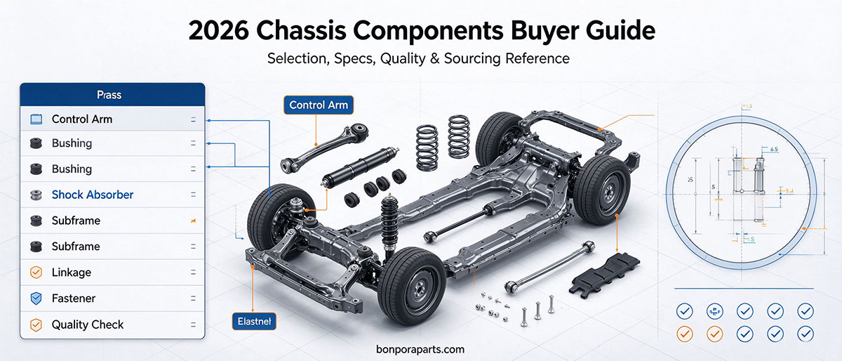
A dust cover material specification has to fix four numbers, not one name: the temperature the part actually sees, the bellows compression ratio at full bump, the bead and seat diameters, and the vent. Get those right and a modest EPDM boot will outlast an expensive compound chosen by habit.
What a Dust Cover Material Specification Has to Fix
A dust cover is the least expensive part in a damper assembly, and one of the few that protects the two components deciding whether the damper keeps working. It sits externally on the piston rod, above the oil seal, keeping mud, dust and moisture away from the seal and the rod surface while shielding what is underneath from heat and UV.
Most enquiries describe the part in one line: a vehicle, a model year, an OE number. That finds a catalogue entry, but it is not a specification. Four decisions remain open, and each shows up later as a distinct failure mode:
Compound and grade reference. EPDM, NBR, NR, PU, TPE and nylon PA66 are all used in production. The family name does not define the cure system or the antiozonant package, and two suppliers can both quote EPDM and deliver different service life.
Temperature rating. A family's qualification tests and a compound's practical range are two different statements, and neither is a promise for a specific part in a specific vehicle.
Bellows geometry. Free length, rib count and wall thickness at the fold decide whether the sleeve survives the stroke without binding or over-stretching.
Fixing and venting. A bead, a wire ring, a plastic collar or a cable tie each behave differently after three winters, and a blocked vent turns the boot into a pump.
This page covers those four decisions and the two gates where a buyer can still catch a mistake. Range planning and OE cross-referencing are covered across the rest of the dust covers range.
Start From the Temperature the Dust Cover Material Actually Sees
Two numbers get confused in quotation tables. The first is the qualification envelope: the family is tested to IATF 16949 system requirements, with test items including hardness, tensile strength, ozone resistance and high and low temperature resistance from -40 C to +100 C. The second is each compound's practical range, which the material table on our Bonpora dust cover range quotes as roughly -40 C to +120 C for EPDM and nylon PA66, -40 C to +100 C for TPE, -30 C to +100 C for NBR, -40 C to +70 C for NR and -30 C to +80 C for PU.
Neither figure is an operating guarantee. The first is the envelope the test programme covers; the second is described on the same page as orientation only, because suppliers shift formulations with fillers and plasticisers, and a compound that meets a range on a data sheet can sit outside it in a real assembly. Measure at the part, at the end of a hot run: a rear boot may see little more than ambient, while a strut boot near a brake disc or exhaust can run far above bay temperature. Where measurement is not possible before the first order, typical industry practice is to add a 20-30 C margin to the bay ambient and confirm on the first batch - a figure to verify with the supplier, not to copy.
| Duty case (illustrative at-part peak) | What the specification should ask for | Listed compounds that fit |
|---|---|---|
| Rear damper, mild climate, 60 C | Min -30 C, max +90 C | EPDM, NBR, NR, PU and TPE all sit inside this window |
| Front strut near the brake, hot climate, 95 C | Max rating at least +115 C | EPDM or nylon PA66 (about +120 C); TPE at +100 C leaves no margin |
| Light commercial near the exhaust, 120 C | Max rating +130 C or a heat shield | No flexible grade in the table has margin; specify a deflector or shield |
| Cold market, -35 C winter start | Low end at or below -40 C | EPDM, TPE, NR and PA66 keep flexibility; NBR and PU (-30 C) sit at the edge |
The temptation is to ask for the widest range on the list. Range, however, is bought with something else. NBR buys oil resistance by giving up the cold end. PU buys abrasion resistance at a narrower window than EPDM and suits stone damage duty. NR is inexpensive and flexible but stops at about +70 C. Naming the measured temperature and the exposure lets a supplier propose a grade, not guess at "the good one".
Bellows Geometry: Turning the Damper Stroke Into a Compression Ratio
The corrugations do the work: they let the cover follow suspension travel without permanent stretch, and the profile has to match the actual stroke rather than a general size. Too few ribs and each fold stretches further on every cycle, so it cracks earlier; too many and the folds bunch at full compression and rub, wearing the wall from inside.
Three measurements on the damper turn that into numbers: the free length of the cover as fitted at ride height, its length at full droop, and its length at full bump. From these, two ratios do most of the work in a specification review.
Stretch ratio is extended length divided by free length. Typical industry practice keeps it at or below about 1.15 to 1.25. Above that the sleeve is under tension at droop, and tension is what pulls a bead off a rod and splits rubber at the clamp.
Compression ratio is compressed length divided by free length. Typical practice keeps it at or above roughly 0.55, so the folds never close solid on each other. Below that, adjacent folds rub and the cover wears through from the inside out.
The table below applies both ratios to one damper with 245 mm at full droop and 130 mm at full bump, and three candidate covers offered against it.
| Candidate | Free length | Stretch ratio (245 mm) | Compression ratio (130 mm) | Verdict |
|---|---|---|---|---|
| A | 235 mm | 1.04 | 0.55 | At the compression floor: folds close and rub, wear marks at the crown |
| B | 210 mm | 1.17 | 0.62 | Inside both bands, with margin on each side |
| C | 190 mm | 1.29 | 0.68 | Over the stretch limit: tension at droop, splits near the clamp |
The table does not call cover B a better part, only the profile that matches this stroke; the same B on a damper with a longer droop would fail the first ratio, and the same C on a shorter one might pass.
Rib count is the second-order variable, but it belongs on the drawing. Pitch - the bellows length divided by the rib count - is the practical number: typical practice for a 2 mm wall sits around 25 to 35 mm of pitch. Two covers with the same free length and different rib counts are not interchangeable.
Wall thickness is a trade-off rather than a target. A thin wall flexes easily and punctures on stones; a heavy wall resists impact and stiffens in cold weather, which moves the failure from the wall to the fold. State the figure at the fold, not at the straight section, which is thinnest after moulding.
Venting deserves a line on the drawing too. Some designs carry a breather feature or a loose fit at one end so air moves in and out as the volume changes, instead of the sleeve inflating and collapsing like a pump. A vent sealed by grease or a band fitted too high produces a ballooned cover that leaves its seat.
If the damper dimensions and the at-part temperature are known, the compound and the profile can be confirmed against an existing tool or quoted as a new one. Request the specification sheet or a sample pair and the review starts from numbers, not a description.
The Fit Dimensions That Decide Whether the Cover Stays On
Seven dimensions belong on the drawing for a flexible sleeve: piston rod diameter, cylinder or seat diameter at the lower end, extended length at full droop, compressed length at full bump, free length in the fitted state, clearance to the spring and body, and colour. The first four decide fit; the rest decide whether the part survives its first year.
The fixing method is where most early failures begin. Gripping can be an interference fit on a bead, a wire ring, a plastic collar or a cable tie, each with a different tolerance for an oversize rod or a worn groove. A sharp edge under a clamp is a frequent cause of early failure, and a reused single-use clip is a common reason a replacement cover fails sooner than the original.
Clearance is the dimension most often checked in the wrong place. Where the cover sits close to a coil spring, the gap has to be confirmed through the full steering and suspension range, not at ride height alone. Rubbing marks on one side of a returned part usually mean it was verified with the vehicle standing still.
A Specification Worksheet You Can Attach to the RFQ
The worksheet below is the practical output of everything above: fourteen fields, each with what to write and the check that catches it at goods-in. Two suppliers quoting against it are quoting the same part - including the dust cover material fields a part number leaves open.
| # | Field | What to write | Checked at goods-in by |
|---|---|---|---|
| 1 | Part and references | Own number plus the OE references the part must cover | Label against the purchase order |
| 2 | Compound | Family plus the supplier's grade reference, not the family alone | Certificate of conformance and batch record |
| 3 | Hardness | Shore A range plus the measurement location, normally a flat area away from ribs | Durometer, three readings per part |
| 4 | Temperature rating | Minimum and maximum in C, with the test basis behind each figure | Test report for the compound |
| 5 | Free length | Millimetres with a tolerance | Calliper on three parts |
| 6 | Extended and compressed length | Both figures, from the drawing rather than a catalogue | Compared with the dimensional report |
| 7 | Upper bead | Diameter, profile and groove engagement | Gauge on three parts |
| 8 | Lower seat or lip | Diameter and collar style | Gauge plus a visual check for lip tears |
| 9 | Ribs | Count and pitch in millimetres | Count and measure one part |
| 10 | Wall at the fold | Thickness with a tolerance, measured at the fold | Section or ultrasonic reading |
| 11 | Vent | Diameter and position, or an explicit "no vent" | Probe every part on a sample basis |
| 12 | Fixing | Bead, ring, collar or tie, plus the clip part number and whether it is single use | Visual and a twist test |
| 13 | Appearance and marking | Colour, finish and the date code position | Visual |
| 14 | Packing and documents | Dividers between parts, no compression on the bellows, CoC plus dimensional, hardness, ozone and low temperature results | Carton opened and label read |
Two fields are usually missing when a first order goes wrong: the grade reference, left as a family name, which allows a compound substitution that passes every dimensional check; and the vent, left unstated, so a supplier who seals it and one who opens it both believe they have met the drawing. The production controls behind fields 2 to 4 are set out in the dust cover manufacturing guide.
Two Inspection Gates: Goods-In and After Fitting
Inspection of a soft part feels forgiving, which is why it is usually skipped. Two short gates cover most of the risk: one at goods-in on a sample from the shipment, one on the first vehicle.
Gate one: goods-in checklist
Read the label against the purchase order: part number, quantity, batch code, production date.
Measure free length on three parts against the drawing tolerance.
Measure bead diameter on the same three parts; reject a rolled or deformed bead.
Measure the lower lip or seat diameter, and look at the lip for tears.
Count the ribs and measure pitch; one rib fewer is a different part, not a variant.
Measure wall thickness at two opposite folds, where moulding variation shows first.
Take three hardness readings on a flat area, away from the ribs.
Probe the vent, if one is specified, and confirm it is open, not moulded closed.
Inspect flash on the bead seating face; flash there is a leak path no dimension catches.
Flex the bellows by hand through its full stroke; the folds should not bind or snap.
Check the packing state: parts separated, bellows not compressed against each other.
Confirm documents: certificate of conformance, bead and seat dimensional results, hardness, and the dust cover material test results for ozone and low temperature on a new part number.
Gate two: after fitting
Confirm the bead is seated: a correctly seated cover cannot be rotated freely on the rod.
Confirm the clip or collar is new and the right part number, not the one removed.
Confirm no band, grease or paint crosses the vent.
Confirm the cover sits at its free length, not pulled down under tension.
Check clearance at full bump and full droop, wheels straight and then on full lock.
Check for twist along the bellows; the folds should run parallel, not helical.
Check spring seat, hose and bracket routing through the travel, not only at ride height.
Road test over a speed bump and a rough section, listening for a new knock.
Where a cover comes off
Separation is rarely a single cause, and the location tells you which one applies. A bead that rolled during fitting usually went on dry, over a thread or burr. A clean cut under the clamp points to a sharp edge or an over-tight band. A torn lower lip usually means the seat diameter was one size too large. A crack at the fold crowns is a drawing problem - too few ribs for the stroke - and repeats on every unit. A ballooned cover that left its seat had a blocked vent.
What a Wrong Bellows Specification Costs
The commercial case for a rated dust cover material is smaller than the unit price difference suggests, and larger than most buyers expect. Take 12,000 covers a year, an unrated cover at 0.58 and a rated one at 0.69, and a claim costing the part plus 0.35 hours of workshop time at 22 per hour plus 1.30 in handling and freight. All figures here are illustrative, not a quotation.
| Line | Option A, unrated | Option B, rated |
|---|---|---|
| Unit price | 0.58 | 0.69 |
| Annual part spend, 12,000 pcs | 6,960 | 8,280 |
| Failure rate in service | 3.0% | 0.8% |
| Claims per year | 360 | 96 |
| Cost per claim, part plus labour and handling | 9.58 | 9.69 |
| Claim cost per year | 3,448.80 | 930.24 |
| Total annual cost | 10,408.80 | 9,210.24 |
The rated cover costs 1,320 more in parts and returns 2,518.56 in avoided claims. The break-even is 1,320 divided by 9.58, about 138 claims a year - 1.15% of volume. If the unrated cover fails less often than that, it is genuinely the cheaper choice, and the question becomes measurable rather than philosophical.
A geometry error does not behave like that. A cover stretched at droop fails at the clamp on a large share of units rather than 3% of them, and it fails in the first season, half way through the warranty period.
Both cases point to the same buying habit: put the four numbers on the drawing, check them twice, and let the price follow the specification rather than replace it.
Frequently Asked Questions
Can I order a dust cover by OE number alone?
An OE number identifies an application, not a part geometry. Vehicles sharing a nameplate can use different strut and boot combinations, and a number carried across catalogues without measurement is unverified. Use it to start the search, then confirm bead diameter, seat diameter, free length and rib count against a dimensional table.
Does a wider temperature range always mean a better dust cover material?
No. Range is bought with other properties. A grade extended at the top end often gives up flexibility at the cold end, and an oil resistant grade such as NBR gives up low temperature performance to get there. The right question is the measured temperature at the part plus the exposure, not the widest window on a data sheet.
How can I tell whether the bellows will bind before I have production parts?
Measure the damper, not the old cover: free length at ride height, length at full droop, length at full bump. Divide to get the stretch and compression ratios, then compare them with the supplier's drawing. A sample can then be flexed by hand through the same stroke before release.
Should hardness be specified on a dust cover?
Yes, but as a range with a measurement location rather than a single number. A flat area away from the ribs is the usual place, because a reading on a fold reflects the section geometry more than the compound. A single figure without a tolerance leaves too much room between batches.
A cover that is slightly stretched still fits. Is that acceptable?
It will fit and it will fail early. A cover fitted under tension pulls on its bead at every rebound stroke, which is the mechanism behind splits near the clamp and covers that come loose on one end. Fit at free length with a new clip; if the only available part needs stretching to reach, the profile is wrong for that damper.
- Prev.:EV Underbody & Battery Impact Protection vs ICE Vehicles
- Next.:Nitrogen Gas Bladder Sourcing: Rubber Grade, Burst Test