sales@bonporaparts.com
0086-10-64988621
English
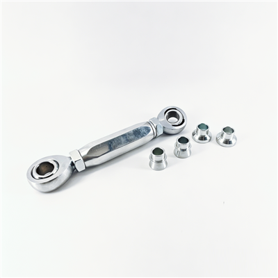
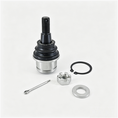
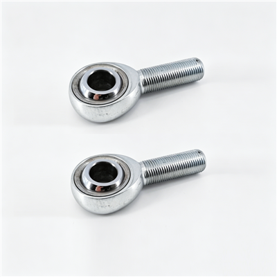
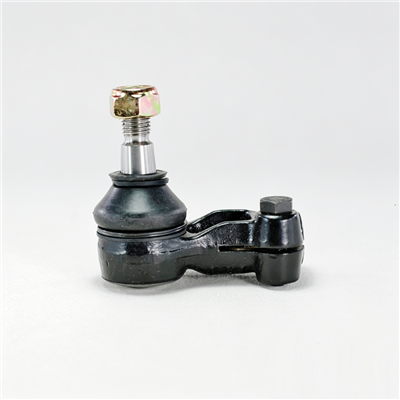
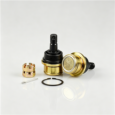
A link and ball joint assembly connects moving parts of a suspension system. Typical examples are the stabilizer link and the suspension link. Ball joints are installed at the ends of control arms, tie rods and similar components, where they form a spherical hinge. The link transmits force and motion and allows a certain range of swing, and the ball joint adds multi-directional rotational movement while carrying both axial and radial loads.
In a fleet, that duty repeats thousands of times per day on roads the vehicle did not choose. The published quality guarantee is one year or 30,000 km, applied to looseness or abnormal noise. Those two symptoms are the fleet signals to watch, and they are both measurable before a driver reports anything, which is what makes a planned programme cheaper than a reactive one.
A joint does not wear at a steady rate across a mixed fleet. Three factors dominate the rate: how often the suspension reaches full travel, how much road salt and grit reaches the dust cover, and whether the link carries an unusual side load from a modified or overloaded vehicle.
Vans on urban delivery routes accumulate more steering and roll cycles per kilometre than long-distance trucks, so they reach the same joint wear at a lower odometer reading. Vehicles that regularly run at or near the gross weight limit load the stabilizer link harder on every corner. Banding by route and load profile explains far more of the spread in replacement age than the odometer alone.
A dust cover that survives a dry climate can split within a few winters where de-icing salt is used. The cover is the part that decides joint life, because once it splits the grease leaves and water enters. In cold markets, plan the inspection cycle around the end of the salt season rather than the calendar year, since that is when the damage becomes visible.
| Duty band | Typical profile | Suggested inspection interval |
|---|---|---|
| Light urban | Delivery cycles, low speed, high steering activity | Every 10,000 km or 3 months |
| General mixed | Mixed urban and highway, normal load | Every 20,000 km or 6 months |
| Heavy or towing | Frequent near-limit load, rough surfaces | Every 10,000 km or 3 months, plus after any impact damage |
| Salt belt or coastal | De-icing salt or sea air exposure | Every 10,000 km or 3 months, with a cover check after each winter |
The inspection does not need a lift or a workshop slot in most cases. With the vehicle on level ground and the wheels straight, a technician can cover the visible joints on both axles in a few minutes.
Look first at each dust cover for splits, hardening, grease loss and a displaced retention ring. Then check the link body for a bend, a crack at a welded end or a bright wear mark where it has contacted another component. Finally, with the suspension loaded, hold the link and feel for perceptible movement while an assistant rocks the steering slightly. A joint that has begun to loosen usually shows itself as a small movement with a light knock rather than as a large free play.
A knock heard in a road test can come from several components, so record a measured value where access allows. Ask the workshop to measure axial play with a dial indicator and to record the result in millimetres alongside the odometer reading. The comparison between two service visits is more useful than any single reading, because the trend tells you how much life remains.
| Recorded field | Why the fleet programme needs it |
|---|---|
| Odometer at inspection | Builds a wear rate per vehicle for the same reference |
| Measured axial play | Turns a subjective check into a trend line |
| Dust cover condition | Distinguishes a worn joint from a contaminated one |
| Action taken | Shows whether the interval is too long or about right |
| Route or duty band | Separates a route problem from a part problem |
| Part reference fitted | Allows comparison between suppliers and batches |
Letting the joint fail before replacement costs more than the part: a separated link creates secondary damage, a roadside call-out and a vehicle off the road at an unscheduled time. A planned interval moves the work into a service visit where the labour is already booked.
Start with the duty band recommendation, then track two numbers for one year: the average replacement odometer for each reference and the number of joints replaced early because of a split cover. If most replacements arrive soon after the suggested interval, extend it slightly. If early replacements cluster in one duty band, shorten the interval for that band only rather than for the whole fleet.
Links and ball joints share access with the stabilizer bar and the control arm, so schedule replacements together with the work that already requires the same area to be opened. Grouping also reduces the risk of a second alignment charge. Where the joint is pressed into an arm rather than bolted, confirm the workshop has the press adapters before the vehicle is booked.
Suspension references multiply quickly across a mixed fleet, so stock planning works best when it is tied to the vehicles rather than to the catalogue.
| Stock group | Basis for the quantity | Cover policy |
|---|---|---|
| Core references | Fitted to the most numerous platform in the fleet | Hold two service cycles of expected demand |
| Secondary references | Smaller platforms and older vehicles | Hold one cycle, reorder on the first use |
| Safety stock | Any reference with a single supplier | Hold one additional set per vehicle age group |
| Consumables | Fixings, covers and grease where the joint is serviceable | Hold with the core references |
Store the parts flat and protected. A quenched stud with a machined face will show surface rust in a damp store, and a rusty part fitted to a vehicle becomes a warranty argument later. Keep the lot marking on the packing visible so a batch can be traced if a fault appears.
Decide per reference whether the work stays in the own workshop or goes out. The deciding factors are the tooling for pressed joints, the need for alignment after the work, and the volume of the reference in the fleet. A high-volume bolted link is well suited to in-house work, while a pressed ball joint in a forged arm may be cheaper to outsource when volumes are low, simply because the pressing and alignment equipment is already there.
Either way, insist on the same installation rules that the manufacturer sets out: new fixings where the specification calls for them, correct tightening at ride height where the joint has a rubber bush on the other end, and a light check of the dust cover after the joint is seated. Most early failures traced back to a workshop are caused by a twisted cover or by tightening at full droop, not by the part itself.
The published terms cover one year or 30,000 km for looseness or abnormal noise. To use that guarantee without an argument, keep four items with each claim: the part reference and lot, the fitted date and odometer, the measured axial play or the recorded noise finding, and a note on the installation if it was done in-house. A claim supported by a measurement is far easier to settle than one supported by a driver description alone.
Keep a short record of rejected claims as well. A pattern of claims rejected for installation damage usually points at a training gap or a missing tool, and fixing that is cheaper than continuing the argument with the supplier.
After a year of records, review the data with three questions. Which references consumed the most labour hours per vehicle? Which duty band produced the earliest replacements? Did any batch of a single reference fail noticeably earlier than the same reference from another batch? The answers tell you where to change the interval, where to change the part specification and where to change the supplier. A fleet that reviews this once a year generally finds that a small change to one interval is worth more than a general price negotiation.
Between every 10,000 and 20,000 km depending on duty. Urban delivery, heavy load, salt belt and coastal vehicles belong at the shorter interval, and general mixed routes can use the longer one. Add an inspection after any recorded impact to a wheel or kerb.
Usually yes. Inspect the dust cover for splits and grease loss, check the link body for a bend or a contact mark, and measure axial play with a dial indicator where access allows. A measured value recorded with the odometer reading gives a trend that a road test cannot.
Replacing both sides of an axle together is usually worthwhile when the two joints have covered the same distance, because the second one is close to the same wear state and the vehicle is already in the workshop. Where one side failed early because of impact damage, replace only the damaged side.
A split or hardened dust cover is the single largest cause, because it lets water and grit reach the bearing surface. Road salt, near-limit loading and repeated full suspension travel all accelerate cover damage, so those are the vehicles to inspect first after each salt season.
Start from the link and ball joint range to confirm the references fitted across the fleet, read the failure analysis guide to match a symptom to its cause before ordering parts, and keep the installation guide with the workshop procedure so that a cover is never seated twisted. The specification outline lists the base values to compare against your measured readings, and the covering control arm range is worth reviewing when the same service visit opens the lower arm. For fleet quantities, batch planning and stock arrangements, use the contact page.