sales@bonporaparts.com
0086-10-64988621
English
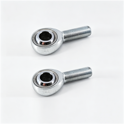
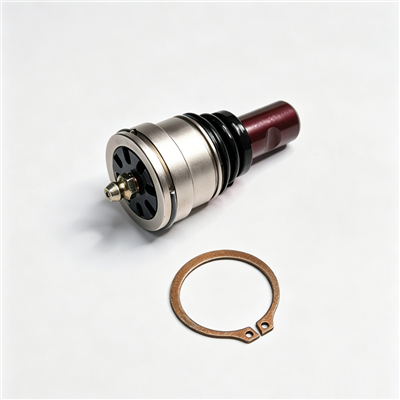
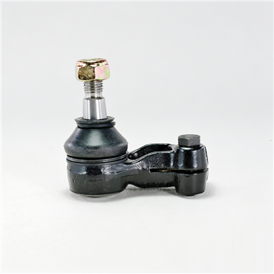
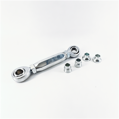
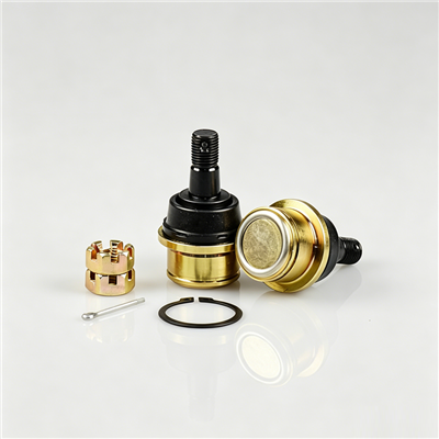
Links and ball joints connect the moving parts of the suspension system. A ball joint is installed at the end of a control arm, a tie rod or a similar member and forms a spherical hinge. Bonpora lists two duties for the group: a link transmits force and motion while allowing a certain range of swing, and a ball joint enables multi-directional rotational movement while withstanding both axial and radial loads. The link body is carbon steel or aluminium alloy, the ball joint housing is polyoxymethylene or nylon, and the ball stud is quenched alloy steel. Quality control inspects starting torque, swing torque, axial play and dust cover durability, the warranty for looseness or abnormal noise is one year or 30,000 km, and customisation covers link length, ball stud diameter and dust cover material. This guide covers the fitting job: how to release a joint without damaging it, how to press or screw a new joint to the correct depth, how to seat a taper so that it holds, and what to check before the vehicle leaves the workshop.
The same joint type appears in several positions, and each position changes the order of work rather than the principle.
At the end of a control arm the joint is loaded by wheel forces and works through the full suspension travel. At the end of a tie rod the joint carries steering motion and must move smoothly so the driver keeps steering feel. At each end of a stabiliser or suspension link the joint works through a smaller angle at a higher cycle count. In every case the joint is held by a taper and a nut, by a screwed housing, or by a pressed and staked housing, and the fitting method follows that design.
A press fit joint is pushed into the arm or the link with a controlled interference and then retained by a snap ring, a stake or a cover plate. A screw fit joint is threaded into the housing and locked. A bolt fit joint is fastened to the arm with bolts or a clamp. Identify which design is on the vehicle before starting, because the removal method differs completely and an incorrect method damages the housing.
The joint carries wheel loads, so the vehicle and the suspension must be supported before any fastener is released.
Raise the vehicle on a level surface, support it on stands at the manufacturer points, and keep the jack as a secondary support. Support the arm or the link with a stand so that it cannot drop or swing when the fasteners come free, because a released suspension member moves sharply under spring load. Never work under a vehicle held only by a jack.
Do not strike a joint body or a taper with a hammer to release it. A blow deforms the housing, changes the preload and can crack the seat, and the damage is invisible until the joint is in service. Use a separator or a puller, and keep heat away from a joint that has a polymer seat and a dust cover, because both are temperature sensitive.
Staging the correct tools before the vehicle goes up is what prevents a joint being released and left open while a tool is fetched.
A separator or a puller appropriate to the taper size, sockets and spanners for the nut and the clamp, a torque wrench covering the largest fastener on the job, a pry bar for the check afterwards, and a wire brush for the seat. Add a torque angle gauge where the specification calls for an angle rather than a value.
A press or a joint installation tool with the correct adapter, a set of receivers sized to the housing rather than to the joint, a depth gauge or a marking method to confirm insertion depth, and a new retaining ring or cover plate where the design uses one. If the design uses a dust cover supplied separately, order it with the joint rather than reusing the old one, since the cover is the part that protects the bearing surface.
| Stage | Tool or item | Purpose | Note |
|---|---|---|---|
| Support | Jack, stands, chocks | Hold the vehicle and the suspension safely | Support the arm or link before releasing it |
| Release | Separator or puller | Free the taper without damage | Never strike the joint body |
| Remove | Press, adapters and receivers | Extract a pressed joint squarely | Support the housing around the bore |
| Refit | Press or installation tool, depth gauge | Insert to the specified depth | Stop at the specified position, not at force |
| Secure | New nut, ring or cover plate | Retain the joint and hold the preload | Replace single use items |
| Confirm | Torque wrench, angle gauge, pry bar | Apply and verify the specified values | Use the manufacturer data for the vehicle |
Two short records make the refit easier and the final check meaningful.
Note the steering wheel position with the wheels straight ahead, and record the alignment values where the equipment is available. A tie rod joint change moves the toe setting, so the baseline shows whether the steering wheel position has to be corrected afterwards. Mark the position of any adjusting sleeve or lock nut with a pen before loosening it.
Clean the taper seat and the thread before ordering the replacement, and note the condition. A polished ring on the taper, a damaged thread or a worn seat is a reason to inspect the mating part as well, because a new joint fitted into a damaged seat will lose clamp load again. Where the arm or the link bore is damaged, the complete assembly is the correct part to order rather than a joint on its own.
Work in a fixed order so nothing is released while still loaded.
Loosen the nut but leave it in place on the last threads so the joint cannot spring apart, then apply the separator or puller to the housing and release the taper. Remove the nut and separate the parts. Where the taper resists, apply penetrating oil and allow time rather than increasing force, because a taper that has to be hammered out usually indicates a seat that has already been damaged.
Support the housing around the bore so the load path passes through the tooling rather than through the arm. Press the joint out squarely and steadily; a joint pressed at an angle scores the bore. On a screwed design, use the correct socket rather than a pipe wrench, and count the turns where the design has a defined insertion depth. On a link with a joint at each end, release both ends before pulling the link out, so that neither joint is loaded at an extreme angle during removal.
The fit is where the service life is decided, so the preparation matters as much as the tooling.
Clean the bore or the thread and remove corrosion without removing material. Check the bore for roundness, because a pressed joint in an oval bore will not hold its interference and will move in service. Check the seat for the taper class and clean it of grease unless the specification states otherwise, since friction at the taper is what transmits the load.
Press or screw the joint in squarely until the specified depth or the retaining feature engages, then fit the new retaining ring or cover plate. Do not judge the end point by the force on the tool, because a joint that is pressed too far can be damaged and a joint pressed short of the position will not be retained correctly. Confirm the insertion depth with a gauge or against a marked reference.
Where the cover is a separate item, fit a new one and check that it sits without twisting or pinching, and that the retention groove is fully engaged. The cover is the only protection for the bearing surface, and a cover folded during fitting allows water in from the first day of service.
A link is only correct when both of its joints sit at their neutral angle with the vehicle at ride height.
Locate the link with the suspension at its normal ride position rather than at full droop. Fitting a link at full droop forces both joints to hold a permanent angle, which pre-loads the dust covers and adds friction from the first kilometre. Where a link has a ball joint at each end, line up both tapers before tightening either nut.
Push the stud into the tapered seat and confirm that it is fully engaged, then fit the nut and tighten to the specified value or angle. Use a new nut where the manufacturer marks it as single use, and do not lubricate the thread unless the specification states it, because lubrication changes the relation between torque and clamp load. Where a clamp bolt holds the taper, tighten the clamp only after the stud is seated.
| Connection | Typical design | Correct practice | Error to avoid |
|---|---|---|---|
| Ball stud to knuckle or steering arm | Nut on a tapered stud | Seat the taper fully, then tighten to the specified value | Tightening a partially seated taper |
| Joint to arm or link | Pressed with a retaining ring, or screwed and locked | Insert squarely to the specified depth | Pressing until the tool stalls |
| Link to bar or arm | A joint at each end | Locate at ride height so both joints sit neutral | Fitting at full droop |
| Clamp or pinch bolt | Bolt or nut on a split clamp | Tighten after the stud is seated | Clamping before seating |
Three checks confirm that the work is complete, and all three take less time than a return visit.
Move the joint through its working angle by hand and compare the resistance with the opposite side. Check the stud for float, which should be within the specification for a new joint, and confirm that the dust cover is correctly seated with no twist. Where the design allows a starting torque measurement, take the reading in the stated window and at the stated temperature.
With the wheels straight ahead, check that the steering wheel is centred. A tie rod joint change alters the toe setting, so the alignment should be measured and reset where an adjuster exists. On a control arm or a link replacement, the alignment check confirms that no mounting point was disturbed during the job.
Drive at low speed over a surface that reproduces the original complaint, listening for the knock that the customer reported and checking that the steering returns to centre normally. Then drive at road speed to confirm that no new vibration has appeared. Re-check the wheel bolt torque after a short distance, as with any wheel removal.
The faults below account for most repeat visits after a joint or link job, and each one is avoidable.
Almost all of them come from taking a shortcut in one of three places: releasing a taper with force, fitting at the wrong suspension position, or assessing the insertion depth by feel. Working in the order set out above removes the temptation.
| Error | Result | Correct practice |
|---|---|---|
| Striking the joint to release a taper | Deformed housing, changed preload, early failure | Use a separator or puller |
| Incomplete taper seating | Loose joint and loss of clamp load | Seat fully, then tighten to specification |
| Joint pressed too far or at an angle | Damaged joint or scored bore | Insert squarely to the specified depth |
| Link fitted at full droop | Pre-loaded joints, split covers, noise | Fit at ride height |
| Reusing a single use nut or the old cover | Reduced clamp load, water ingress | Fit new retaining and sealing parts |
| Skipping the alignment check | Off centre steering wheel and tyre wear | Measure and reset the toe where adjustable |
A press or a dedicated installation tool is necessary, because the joint has to be inserted squarely and to a defined depth. Drawing a joint in with a bolt and a stack of washers risks an angled insertion that scores the bore.
Where the design has a separate cover, fitting a new one is normal practice. The cover is the only barrier protecting the bearing surface, and its retention groove is a wear feature, so reusing an old cover trades a small saving against a much shorter joint life.
Yes. The tie rod sets the toe, so the setting should be measured and reset after the joint or the rod is changed, and the steering wheel position checked with the wheels straight ahead.
Move it through its working angle and compare with the opposite side, check the stud for float, confirm the cover is seated without twist, and where the design allows, take a starting torque reading. Then confirm the steering position and carry out a road test.
Send the vehicle details, the joint position and the required stud diameter or dust cover material to the technical team at Bonpora Parts and Components Co.,Ltd. so that the joint or the complete link arrives ready to fit. The link and ball joint range shows the assemblies available, the selection and specification guide explains the four inspection values, the failure analysis covers how a joint is assessed, and the custom development service handles link length and stud diameter requirements.