sales@bonporaparts.com
0086-10-64988621
English
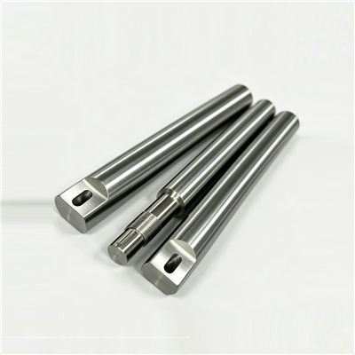
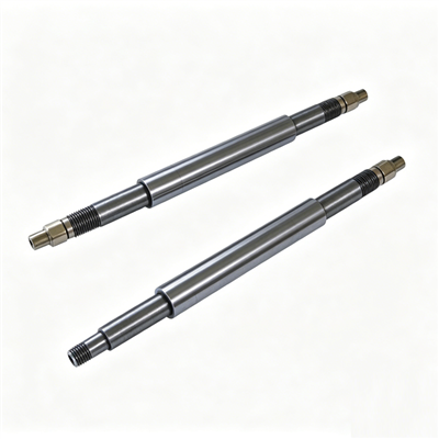
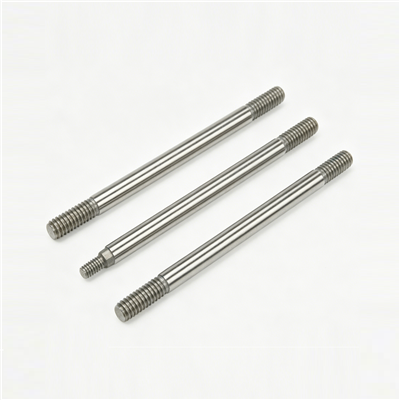
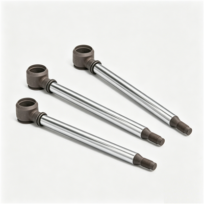
The source row describes the shock piston rod as the core moving component of a shock absorber, made from high strength carbon steel such as S45C or S55C or an alloy steel such as 40Cr, with surface induction hardening or carburising treatment. During compression and rebound it transmits the relative motion between the wheel and the body, drives the piston through the oil to generate damping force, and works as the guiding and sealing mating surface that carries bending load and sliding friction.
That last duty is what makes manufacturing control decisive. A rod can pass every dimensional check and still destroy a seal within a few thousand kilometres, because the failure mechanism is a local surface defect rather than a global dimension. Pitting, a plating nodule, a grinding mark left across the running surface or a residual bow from straightening all concentrate load on the seal lip. This article follows the production sequence and marks the control point that governs each risk.
The first control is at goods inwards. Bar stock should arrive with a mill certificate showing grade, heat number and chemical composition, and with the dimensions verified on receipt. Where a customer drawing specifies S45C, substituting another medium carbon steel because it was in stock changes the hardenability response at step three, even if the finished rod looks identical.
Bar is cut to length with allowance for facing and, where required, for the end features. Cut length is recorded against the production order so that a finished rod can be traced to the bar lot. Deburring at this stage prevents handling marks that would otherwise show up on the finished surface.
Batch cards should follow the lot through every operation. In an audit, the ability to connect a packed rod to a bar heat number and an oven chart is the difference between a process and a hope.
The rod is machined to its basic geometry: the running diameter with grinding allowance, the shoulders or steps that locate it, and the end connection. The source row notes that custom lengths, diameters, surface treatments and end connection types are all available, which means the same production line has to handle both catalogue parts and drawing parts.
Two controls matter here. First, the grinding allowance must be sufficient to remove the machining marks in step four rather than merely reduce them. Second, the transition radii between diameters must be machined as drawn, because those are the points of stress concentration. A sharp internal corner is a fatigue crack waiting for the first impact.
Where the end is to be threaded, the thread quality is inspected at this stage rather than after plating, because a plating build-up can make a thread tight and a re-cut after plating removes the protection.
Induction hardening raises the surface hardness while leaving a tough core, which is why it is the usual process for a sliding rod. The recipe is power, frequency, traverse speed and quench. Increase the traverse speed and the case becomes too shallow; slow it down and the case deepens but the risk of cracking grows. Case depth is therefore measured on a sectioned sample, not assumed.
The drawing should state a hardness band with a method, and the process should be validated against it. Hardening also introduces distortion and residual stress, which is why straightening follows rather than precedes it.
| Process step | Control point | Verification |
|---|---|---|
| Bar receipt | Grade, heat number, dimensions | Mill certificate and dimensional check |
| Cutting and facing | Length allowance, deburring | Sample measurement |
| Machining | Grinding allowance, radii as drawn | First article inspection |
| Induction hardening | Power, traverse, quench, case depth | Sectioned sample, hardness test |
| Grinding | Diameter, taper, surface finish | Micrometer at three positions, roughness check |
| Plating | Thickness, adhesion, no nodules | Thickness gauge and adhesion test |
| Straightening | Runout within tolerance | Bench check with dial indicator |
| Final inspection | Dimensions, roughness, appearance | Release record against drawing |
Grinding does two jobs: it brings the rod to its final diameter within tolerance and it produces the surface that the seal will run against. Both are sensitive to the same variables, which is the reason a rod with an excellent diameter can still have an unusable finish.
Taper and ovality are the dimensional risks, checked by measuring the rod at three positions along the length and at two orientations. Finish is the surface risk, checked against the roughness band rather than a single number. A wheel that has glazed, a coolant that has degraded or an infeed that is too aggressive will leave a finish that looks acceptable in daylight and fails in service.
Hard chrome provides the low friction running surface and the corrosion resistance expected of a sliding rod. Thickness is specified with a minimum, and adhesion is tested on a sample rather than left to visual inspection. The most damaging plating defect is a nodule: a small raised deposit that scrapes the seal lip on every stroke.
Nitriding and special coatings are listed in the source row as options. Nitriding raises hardness without a deposit and is chosen where corrosion resistance must come from the base material. Special coatings target a specific friction or corrosion requirement. Each finish carries its own masking and preparation rules, so a change of finish is a change of process rather than a substitution of one step.
Plated rods should be handled in sleeves or with soft jaws. A rod that is dropped, gripped in a bare chuck or laid on a bench edge can receive a mark that no inspection plan will catch if final inspection is dimensional only.
Straightening is necessary and also dangerous, because it introduces local stress. The operation should be followed by a stress relief where the specification demands it, and always by a straightness check over the exposed length. A runout that is inside the drawing but concentrated at one point is a common cause of a seal that leaks on one side.
Final inspection should include diameter at three positions, straightness, roughness on a sample, surface hardness on a sample, coating thickness on a sample, and full visual examination under adequate light. The visual stage is where most escapes are caught, and it only works when the criteria are written down.
| Defect | Likely cause | Containment |
|---|---|---|
| Pitting on the running surface | Contaminated plating bath or poor pre-treatment | Hold the batch, strip and re-plate, review bath chemistry |
| Plating nodules | Current density or filtration problem | Reject, review racking and bath control |
| Spiral grinding marks | Excessive infeed or worn wheel | Re-dress the wheel, recheck roughness on samples |
| Insufficient case depth | Traverse speed too high | Verify with a sectioned sample, adjust the recipe |
| Residual bow | Straightening without control | Recheck runout, add stress relief where specified |
| Thread damage after plating | Build-up on a masked area | Re-mask, inspect thread with a gauge |
| Handling marks | Storage outside sleeves | Retrain, supply sleeves at the workstation |
Each entry pairs a symptom with a process cause, because a defect that cannot be traced to a process step will reappear on the next batch.
The source row states IATF 16949 compliance, a service life of 80,000 km or 5 years under normal operating conditions, and a warranty of 2 years or 80,000 km whichever comes first. Those commitments are only maintainable when the production records support them.
Where a rod was produced to a customer sample rather than a drawing, the measured dimensions of the approved sample should be recorded as the reference. That single document prevents most disputes about a repeat order.
From the duty of the damper and the diameter of the rod, then confirmed by a sectioned sample from the first batch. The drawing should give minimum and maximum depth, because both extremes cause problems, one through wear and the other through brittleness.
No. The requirement is a controlled roughness band. A surface that is polished far beyond the specified value can reduce oil retention at the seal lip, which raises friction and running temperature.
Rarely for a long rod, because hardening and grinding both introduce distortion. What can be controlled is how straightening is performed and what stress relief follows it, both of which should be fixed in the process specification rather than left to the operator.
Material certificate, case depth and hardness results, roughness and straightness measurements, plating thickness and adhesion results, and a dimensional report against the drawing. For a sample based rod, add the approved sample measurements.
Bonpora Parts and Components produces shock piston rods to drawing or sample in S45C, S55C and 40Cr, with induction hardening, carburising, hard chrome, nitriding and special coatings, and supplies batch records with the delivery. Review the piston rod range and the piston rod selection guide, compare the shock absorber component range, and see the steel shim range for the internal parts of the same damper. Drawings and sample measurements are handled through the custom parts service or the contact page.