sales@bonporaparts.com
0086-10-64988621
English
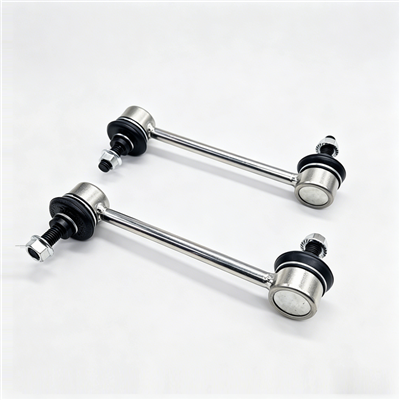
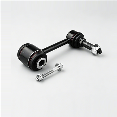
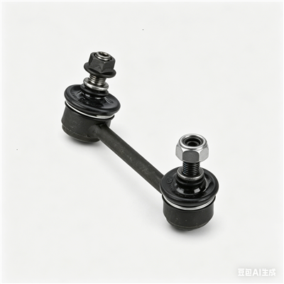
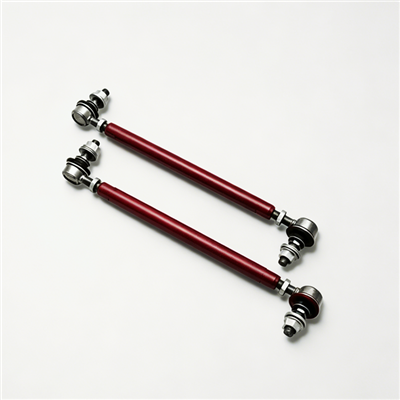
A stabilizer bar, also called a sway bar link assembly point or an anti-roll bar, is mounted on the subframe or the vehicle body, with its two ends connected to the left and right suspension lower control arms or shock absorbers through stabilizer links, which are also known as drop links. It reduces body roll during cornering and improves driving stability by transferring part of the compression deformation from one side of the suspension to the other, which balances wheel load distribution. It is produced from solid or hollow spring steel, with 60Si2Mn and 55Cr3 given as examples.
The whole manufacturing route exists to produce one property: a spring that twists within its elastic range for millions of cycles and returns to its original shape. Every step below is either protecting that property or verifying it.
The bar starts as straight spring steel stock. The grade and the mill certificate are checked against the drawing before cutting, and the diameter is measured at both ends of each length. A supplier who cannot produce the mill certificate for the batch being processed is not able to prove the grade, whatever the marking on the bundle says.
Lengths are cut to suit the developed shape, then the ends are formed. Depending on the design, ends are bent cold, hot formed, upset, flattened or forged into a pad with a link hole. Formed ends are the highest risk area of the whole part, because the geometry concentrates stress and because forming conditions, temperature and cooling rate all affect the local structure.
The formed bar is austenitised, quenched and tempered to a hardness window set by the drawing. This is the step that gives the part its elastic range. Below the window the bar deforms permanently in service; above it the material is more sensitive to cracking at the formed ends and at any surface defect.
| Stage | Parameter that is controlled | Why it matters to the finished bar |
|---|---|---|
| Austenitising | Temperature, time at temperature, atmosphere | Determines the structure available for hardening and limits surface decarburisation |
| Quenching | Quench medium, agitation, part orientation | Controls hardness distribution and the distortion that has to be corrected afterwards |
| Tempering | Temperature and soak time, usually followed by air cooling | Sets the final hardness window and the balance between strength and toughness |
| Straightening | Method, temperature and the amount of correction applied | Heavy cold straightening introduces residual stress and should be avoided |
Hardness is measured on the bar body and on the formed ends, because the ends cool differently and can age differently. Bonpora lists bar hardness as one of the four inspection items for the stabilizer bar, and a buyer should ask for the window, the test positions and the number of readings taken rather than a single value.
Quenching distorts a formed bar, and the correction of that distortion is where residual stress is introduced. A bar that has been straightened heavily is straight on the rack and springy in the wrong direction once installed. Straightness tolerance and the straightening method belong in the discussion with the supplier, not in a footnote of the drawing.
Fatigue strength is the second inspection item Bonpora lists, and it is the one that decides whether a bar cracks at forty thousand kilometres or never cracks at all.
A stabilizer bar is tested in torsional cycling, normally with one arm held and the other cycled through a stated angular or load amplitude. The rig record that matters names the amplitude, the mean load, the frequency and the number of cycles completed without failure. A result quoted without the amplitude cannot be compared with anything.
Cracks almost always start where the stress is highest and the surface is most easily damaged: the inner radius of a bend, the transition where a formed end meets the bar body, and any corrosion pit or handling scratch in those areas. That is why coating coverage at the ends matters as much as the coating on the straight body, and why the ends of the bar deserve extra care in packing and handling.
Permanent deformation, the third inspection item, is the check that the bar returns to its original shape after being loaded beyond its normal service range. The bar is loaded to a test level, the load is removed, and the residual set is measured. Bonpora covers excessive permanent deformation under a 2 year or 50,000 km warranty, whichever comes first, which makes this test the commercial counterpart of the warranty term rather than an academic exercise.
For a buyer, the useful questions are the test load in relation to the service load, the residual set limit, and how the measurement is taken. A permanent set limit stated as an angle at a defined distance from the bar axis is measurable; a statement that the bar is spring steel is not.
Surface corrosion resistance is the fourth inspection item Bonpora lists. On a vehicle, the stabilizer bar lives close to the road surface and is regularly exposed to salt spray, so the coating is a working part of the design.
| Protection route | General character | What to confirm |
|---|---|---|
| Liquid or powder coating over a prepared surface | Colour options, uniform film, good coverage on the body | Surface preparation method and film thickness range |
| Zinc based or phosphate plus topcoat systems | Higher corrosion resistance in road salt conditions | Salt spray hours claimed, and whether the test is on a finished bar |
| Rubber or polymer sleeve in specific areas | Additional protection where geometry traps water | Whether the sleeve is retained positively or relies on friction |
Coating thickness is normally measured on the bar body because that is the easy place to measure. The formed ends, the inner radii and the area under the bushing are the places that actually corrode first. Ask how the process reaches those areas, and whether any mechanical damage from the fixture is touched up before packing.
| Inspection item | Typical method | What the record should show |
|---|---|---|
| Dimensions | Gauge or calliper on length, arm geometry and hole positions | Measured values against drawing tolerances |
| Hardness | Hardness test on body and formed ends | Range, positions and number of readings |
| Fatigue strength | Torsional cycling rig | Amplitude, cycles and result per test piece |
| Permanent deformation | Load to test level, release, measure residual set | Test load and measured set against the limit |
| Corrosion resistance | Salt spray test on finished parts | Hours to the defined corrosion criterion |
| Traceability | Heat number or batch code on the part or the label | Link from finished part to the heat treatment and coating batch |
Records are what turn a warranty claim into a short conversation. When a bar fractures and the batch code can be traced to a heat treatment load and a coating run, the supplier can confirm whether the failure is isolated or shared with other parts in the field, and can decide whether a containment action is needed.
A stabilizer bar is a long, preloaded spring steel part, so packing is a technical step rather than an afterthought. Bars should be supported along their length rather than bundled under their own weight, coated ends protected from contact damage, and each part identified with a batch code and an application reference. For export, add a corrosion inhibiting wrap in humid conditions and a packing list that identifies each reference by vehicle application, because a mixed container of similar looking bars is the fastest way to create a wrong part complaint. Confirm that the container load does not stack weight on the middle of the bars, since a bar that has taken a set in transit will be rejected at goods inwards.
The formed ends cool at a different rate from the straight body during quenching, so they can reach a different hardness for the same heat treatment cycle. Because the ends also carry the highest local stress, checking only the body can miss an end that is outside the released window.
It proves that the bar returns to its original shape after being loaded beyond its normal service range, with residual set inside a stated limit. On a vehicle, that corresponds to an unusually large single wheel input rather than to ordinary cornering.
By torsional cycling on a rig at a stated amplitude and mean load, with the number of cycles completed without failure recorded. The amplitude matters as much as the cycle count, so a fatigue figure should always be read together with the test conditions.
Yes. Film thickness can be measured on finished bars, and salt spray testing is normally carried out on production parts rather than on test coupons. Ask for results from a coated, finished bar so the measurement includes the effect of the coating process.
Bonpora produces stabilizer bars in solid or hollow spring steel to ISO or GB standards, with inspection covering bar hardness, fatigue strength, permanent deformation and surface corrosion resistance, and offers customization of diameter, length, end shape and mounting points with sample validation. Start from the stabilizer bar range, see the specification detail in the anti-roll bar specification guide, read the fitting sequence in the stabilizer bar installation guide, and send drawings or samples through the custom parts page or the contact page for a quotation with inspection records.