sales@bonporaparts.com
0086-10-64988621
English
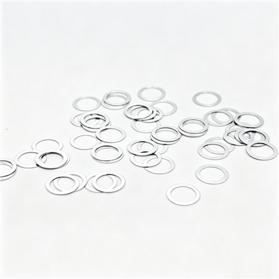
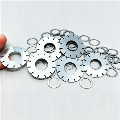
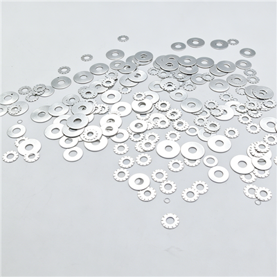
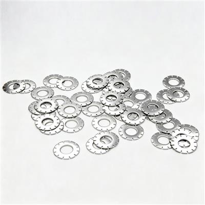
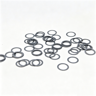
A steel shim, also called a valve shim or shock shim, is installed inside the shock absorber piston assembly. It sits in the piston valve system or the base valve system and works together with valve seats, springs and orifice passages. Standard production grades include Sandvik 20C, SK4 / SK5, C100S, 65Mn, 45# and stainless steel. During the compression and rebound strokes the shim opens or closes as the oil flows, regulating the flow rate through the orifice passages and generating the required damping force. By stacking shims of different thicknesses, diameters and combinations, the damping characteristic is tuned to the vehicle requirement. Under normal operating conditions the expected service life is no less than 100,000 km or 5 years, development and production follow the IATF 16949 quality management system, and a 1 year or 100,000 km warranty (whichever comes first) covers material and manufacturing defects. Custom development from customer samples or drawings is supported for outer diameters of about 4 mm to 60 mm, inner diameters of 0 to 50 mm and thicknesses of 0.1 mm to 1.0 mm.
Because the disc is thin, works under repeated bending and sits in a pressurised oil circuit, it is also one of the first parts an engineer inspects when a damper loses force or becomes noisy. This guide explains how shims fail, what each failure looks like during teardown, which measurements are worth recording, and how to decide between cleaning, replacing and upgrading the stack.
Every failure has to be read against the way the part works. The stack is a set of discs clamped at the centre, free at the outer edge, and it acts as a one way valve that controls how easily oil passes through the piston or the base valve.
As the rod moves into the oil, pressure builds above the piston. Oil is forced through the compression passages and lifts part of the stack. The stiffness and lift of those discs set the compression damping. A shim that has lost its preload opens too early and the damper feels soft, while a distorted disc can restrict the passage even when the pressure is low.
When the rod moves out, oil flows in the opposite direction and lifts the rebound side of the stack. Rebound control usually needs higher force than compression, which is why the rebound discs are often thicker or stacked with a smaller diameter support. Fatigue cracks appear most often on the discs that work hardest, so discs from the rebound side of a high mileage damper are worth examining first.
In a twin tube damper the piston valve controls both directions of the main flow, while the base valve in the bottom of the reservoir adds compression control and helps to refill the working chamber. In a monotube damper the piston carries the full responsibility and the gas charge handles the volume change. The expected failure pattern differs between the two layouts, so the teardown note should always state which design was inspected.
The table below summarises what a technician typically finds, why it happens and how it affects damping. It is intended as a working reference rather than a complete list.
| Failure Mode | Appearance | Likely Cause | Effect on Damping | Corrective Action |
|---|---|---|---|---|
| Fatigue cracking | Short cracks or a broken segment at the outer rim, sometimes with a discoloured fracture face | Repeated bending at high cycle counts, sharp burr or notch at the edge, hardness above the intended range | Local loss of support, sudden drop in force, rattle or knocking | Replace the cracked disc and review edge condition and hardness of the batch |
| Permanent set | Disc no longer flat when placed on a surface plate, visible gap under the rim | Overload, oil overheating, material tempered softer than specification | Early opening, softer than target damping, poor low speed control | Replace the affected discs, check oil condition and operating temperature |
| Edge denting | Flattened or rolled rim, matching mark on the valve seat | Handling damage, loose parts during assembly, debris trapped between disc and seat | Uneven sealing, inconsistent force, noise on small inputs | Replace damaged discs, inspect and clean the seat, tighten cleanliness rules |
| Fretting wear | Polished ring or dark transfer marks where discs touch each other | Micro movement between adjacent discs under pressure cycling | Gradual drift in damping, fine debris in the oil | Replace the worn discs, verify clamping load and stack sequence |
| Corrosion and pitting | Rust spots, pitting, dull or mottled surface on carbon steel discs | Moisture in the oil, humid storage, long idle periods, damaged paint or coating on the damper | Reduced fatigue strength, risk of crack initiation, seat marking | Replace, and consider a stainless grade or an improved surface finish |
| Distortion from assembly | Dished or wavy disc, uneven clamp ring marks | Incorrect stack order, over torque on the retaining nut, burr left on the piston | Asymmetric flow, force scatter between units, noise | Rebuild to the drawing, replace distorted discs, retrain assembly station |
Cracks normally start at the outer edge, where bending stress is highest, or at a burr that acts as a stress raiser. Look for a short radial crack that has not yet opened fully. In many cases the crack face is darker than the surrounding steel, which indicates that it grew over a long period before final separation. When a crack is found, the whole stack should be reviewed rather than only the broken disc, because the others have seen the same duty.
Permanent set is a loss of flatness that remains after the load is removed. It reduces the force needed to lift the disc, so the damper becomes soft in the low speed range even though the parts look undamaged. A simple check is to place the disc on a surface plate or a flat glass sheet and try to slide a feeler gauge under the rim. Any measurable gap beyond the drawing requirement indicates that the disc should not go back into service.
The rim of a thin disc deforms easily. A local dent disturbs the contact with the valve seat, which changes the bleed path and can produce a light knocking noise on small road inputs. Because the seat is usually softer than the disc, a dented disc often leaves a matching witness mark on the seat, which is a useful confirmation during inspection.
Adjacent discs move against each other by a very small amount at every pressure cycle. The contact areas become polished, and material may transfer from one disc to the next. The wear itself is gradual, but the loose particles contaminate the oil and the changed surface profile alters the stack stiffness. Where fretting is found, the clamp load and the stack sequence should be verified before new discs are fitted.
Carbon spring steel relies on the oil and the damper housing for protection. If moisture enters the oil, or if dampers are stored in humid conditions for a long period, rust spots and pits can form. Pits act as stress raisers and reduce fatigue strength, so they should not be ignored even when the disc still looks flat. For humid, coastal or salt exposed applications a stainless grade such as 301 or 304 is often a better choice.
A disc that is dropped, stored loose in a bin or clamped unevenly can arrive at the inspection bench already dished. The most common assembly causes are the wrong stack order, excessive torque on the retaining nut and a burr left on the piston face. Checking the stack against the drawing and confirming the torque value is a quick way to separate assembly faults from material faults.
A consistent inspection routine makes the results comparable between units and between rebuild batches. The following steps cover the essentials for a hydraulic damper shim stack.
| Check | Method | What to Record |
|---|---|---|
| Outer diameter | Vernier caliper or micrometer, three positions | Minimum and maximum reading, comparison with drawing |
| Inner diameter | Pin gauge or caliper where the bore allows | Bore size and any ovality or burr |
| Thickness | Micrometer with flat anvils, at least four points around the rim | Thickness range and variation across the same disc |
| Flatness | Surface plate with feeler gauge, or optical flat for thin discs | Maximum gap under the rim and its position |
| Hardness | Rockwell or Vickers test on a sample disc or on a witness coupon | Value and comparison with the specified range |
| Edge condition | Visual check at low magnification, fingernail or light draw test | Burr height, rolled edge, cracks, dents |
| Surface condition | Visual check under good light | Rust, pitting, fretting marks, coating damage |
Photograph the stack before disassembly and number the discs in the order they were removed. Note the damper model, the mileage or running hours, the oil condition and the gas charge where applicable. The same sheet should carry the measurements, so that a pattern across several units becomes visible. When the same position fails repeatedly, the cause is usually found in the design or the assembly process rather than in a single batch of parts.
The table below links the complaints that reach a workshop or a warranty desk with the shim conditions that can produce them. Other components can cause the same complaint, so the second column lists the additional checks worth completing.
| Complaint | Possible Shim Condition | Additional Checks |
|---|---|---|
| Soft ride and poor body control | Permanent set, softer hardness than specified, incorrect stack order | Gas charge, oil level, worn piston band, valve seat condition |
| Rattle or light knocking on small bumps | Dented rim, cracked disc, debris trapped under a disc | Mounting bushes, rod guide play, top mount bearing |
| Harsh response at low speed | Distorted disc restricting the passage, wrong disc diameter | Bleed path blockage, orifice condition, oil viscosity |
| Force drift between units of the same model | Thickness or flatness variation, hardness scatter | Batch traceability, incoming inspection records, assembly torque |
| Metal particles found in the oil | Fretting wear, cracked edge, corrosion debris | Rod surface finish, cylinder bore wear, oil analysis |
| Oil discolouration with soft damping | Overheating that reduced disc hardness | Operating temperature, duty cycle, oil specification |
Once the inspection results are on the sheet, the decision usually falls into one of three groups.
A disc can normally return to service when it is flat within the drawing requirement, free of cracks, dents, pitting and fretting marks, and within the specified thickness and hardness range. Cleaning must be done without abrasive media that could round the edge or change the surface. Any disc that has been bent during removal should be treated as scrap, because the original flatness cannot be restored by hand.
Replace the whole stack when one or more discs show cracking, when several discs carry fretting or corrosion marks, when thickness varies from the drawing by more than the permitted tolerance, or when hardness is outside the specified band. Mixing new discs into a worn stack is possible in an emergency repair, but the mixed set should be checked on a damper dynamometer before it is released, because the combination of new and old discs rarely matches the original force curve.
Carbon spring steel such as SK5 or 65Mn remains the usual choice for standard hydraulic dampers, because it provides the needed stiffness at a moderate cost. Stainless steel is preferred where moisture, road salt or long storage in humid conditions is expected, provided the stack is reviewed for the different material properties. Every rebuild programme should fix one hardness band and one flatness requirement, and keep incoming inspection records for each batch so that a change in force can be traced back to the parts rather than to the assembly line.
Place the disc on a surface plate or a flat glass sheet and try to slide a feeler gauge of the drawing limit under the rim. Rotate the disc and repeat at several positions. A disc that shows a gap larger than the requirement, or a gap that moves as the disc is rotated, is distorted and should be replaced. Comparing the result with a known good disc makes the judgement easier.
In a field repair it is sometimes done, but the replacement disc should match the original material, thickness, diameter and hardness. Because the remaining discs have already seen the same duty, the safer approach for a warranty or fleet programme is to replace the complete stack and confirm the force curve afterwards.
Not always. Thickness raises the bending stiffness of a disc, which normally increases the force needed to lift it, but the effect also depends on diameter, the number of discs, the support diameter and the sequence in the stack. Changing one disc without reviewing the whole stack can move the damping curve in an unexpected direction, so adjustments are best confirmed by measurement.
Ask for the material grade and heat number, the measured thickness and flatness results, the hardness range, the edge condition requirement and the inspection plan behind the batch. Production that follows the IATF 16949 quality management system is supported by these records, and they make it possible to trace a force complaint back to a specific production run.
Bonporaparts produces steel shims for shock absorbers alongside piston rods, valve parts and other hydraulic damper components. Send a sample or a drawing and the team will confirm the material, dimensions and tolerances for your application. You can review the full steel shim range, read the steel shim material and dimension guide, look at how the parts are made in the steel shim manufacturing process article, browse the related shock absorber parts category, or send your requirements through the contact form.