sales@bonporaparts.com
0086-10-64988621
English
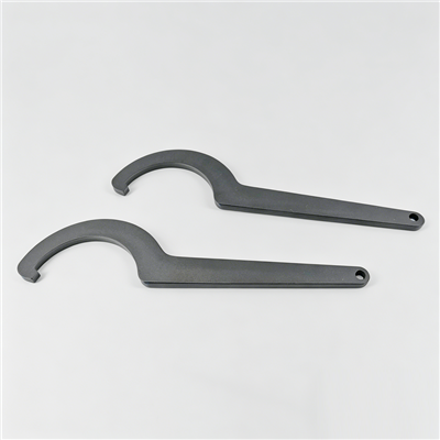
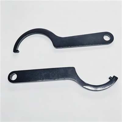
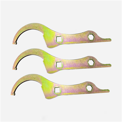
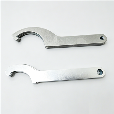
Wrenches and the wider family of process equipment are used in production, assembly, maintenance, or inspection processes. They are not assembled onto the final product and are considered process equipment. Their duties fall into three groups: assisting in installing or removing other parts, such as special wrenches and press-fit tooling, positioning or clamping workpieces to ensure machining or assembly accuracy, and inspecting specific dimensions or performance, such as go and no-go gauges and special inspection fixtures. Bonpora supports custom design based on the customer application scenario, drawings, or an existing tool sample, and can optimise ergonomics and service life as part of that work.
This guide describes how a custom tool is developed from the moment a workshop realises that no catalogue item will do, through reverse engineering and prototyping, to the drawing that goes into production. It is written for tooling engineers, maintenance planners and buyers who are commissioning a special item and want to avoid the usual cycle of trial, complaint and redesign.
Custom tooling is commissioned in one of three ways, and the information required differs sharply between them. Being clear about which route applies prevents the most common delay, which is a supplier waiting for data that the customer has not thought to send.
| Starting point | What the customer provides | What the supplier needs to add | Typical first output |
|---|---|---|---|
| Application scenario | Position, access conditions, force or torque, usage rate | Working end geometry, length and offset, material and hardness | Concept sketch or 3D proposal |
| Drawing | Dimensioned part or tool drawing, tolerance and material | Manufacturability review, hardness, finish, marking | Manufacturing drawing and quotation |
| Existing tool sample | Physical sample, ideally one worn example and one usable example | Reverse engineering, wear correction, improvement proposal | Measured drawing for approval |
When only a scenario exists, photographs from the actual working position are worth more than a paragraph of description. Two phone images taken from the operator position, with a rule placed next to the fastener, usually answer the access, height and line of sight questions at once.
A special tool that has been in service for years is a proven design, but it is also a worn one. Reverse engineering therefore has two parts: recovering the intended geometry, and separating it from the wear. Measure the working end across the flats, the wall thickness, the offset, the overall length and the handle geometry, and record which faces show the heaviest wear. A tool that has opened out by half a millimetre over its life should be reproduced at the original dimension, not at the dimension of the worn part.
The tool exists to fit something. Measure the fastener or feature it works on, or obtain the drawing, and check the relationship between the two. This is where reverse engineering adds most value, because a tool reproduced exactly from a worn sample will inherit a fit problem that the original design may have had from the start. Correcting a loose fit of a few hundredths of a millimetre is often what turns an adequate tool into a good one.
Before modelling, agree a short list of intended improvements. Typical items are a thinner wall for access, a longer handle for reduced effort, a lighter body for ergonomics, a stronger material where the original deformed, and a marking or colour change for tool control. Keeping the list short protects the schedule and makes the improvement measurable after the tools are in service.
| Recorded item | Method | Note for the drawing |
|---|---|---|
| Working end across flats | Calliper, at two depths | Specify the designed value, not the worn value |
| Wall thickness at the load face | Micrometer or ultrasonic where applicable | Minimum thickness governs the material grade |
| Offset and overall length | Height gauge, surface plate | Drives the access envelope |
| Fastener size and form | Measure the mating part | Fit tolerance between tool and fastener |
| Torque transmitted | Published value or measured breakaway | Sets the section and the hardness range |
| Handle geometry | Diameter, length, grip angle | Ergonomics and expected usage rate |
Once the geometry is settled, the material decides whether the tool survives. For a special wrench or a press tool, the choice is usually between a chrome vanadium grade for general torque duty, a chrome molybdenum grade where shock is present, and a through-hardening tool steel where wear resistance at the working face matters most. Specification should give the grade, the hardness range and the location of the hardness check, because hardness at the surface of a small tool is not the same as hardness at the section.
Two details are often forgotten. First, stress raisers: a sharp internal corner where the head meets the shank will crack under repeated load, so a generous radius should be drawn rather than left to the machinist. Second, surface finish: a polished or plated face resists corrosion and reduces notch sensitivity, while a rough ground surface becomes the starting point for a fatigue crack. For clamping components such as soft jaws and protection pads, the material question is different: the contact face must protect the workpiece from marking without taking a permanent set under sustained clamp load.
A prototype is not a formality. It is the cheapest point at which an access problem, a wrong hardness or an awkward grip can still be corrected. Three levels of prototype are worth considering, and the right one depends on what is uncertain.
| Prototype type | Best used to check | Limitation |
|---|---|---|
| Dimensional model or additively made mock-up | Access, reach, swing arc, line of sight | Not suitable for load testing |
| Machined prototype in the final material | Function, torque capacity, grip, real durability | Higher cost, longer lead time |
| Soft tool or low volume batch | Operator acceptance across shifts | Not economical for one off validation |
The trial itself should be run by the people who will use the tool, on the real assembly or machining position, and for long enough to include a full shift pattern. An operator who finds a tool uncomfortable after two hours will find another way to do the job, and the tool will be blamed for the resulting variation.
Ergonomics in a production tool has four practical levers. The first is grip diameter and length, which should suit the operator population rather than an average hand. The second is the working angle, since a tool whose handle axis is badly placed forces the wrist into a position that cannot transmit force reliably. The third is weight, and weight is why a long reach tool is often specified with an aluminium or composite body carrying a steel working insert. The fourth is reaction management: where the torque is high, a reaction arm or a support point removes the need for the operator to resist the full load.
Service life follows from three design decisions: the material grade, the section at the highest stressed point, and the removal of stress raisers. A tool that has a generous radius at the transition, a slightly larger section than strictly needed, and a hardness specified as a range rather than a single value will usually outlast a lighter tool that was optimised only for access.
Before series production, approve a drawing that states the material grade, the hardness range and the check location, the critical dimensions with tolerances, the surface finish, the marking, and the inspection to be performed on the batch. For inspection tooling, add the gauge tolerance, the wear allowance and the identification number. Approval should be recorded against a first article sample, and the sample retained so that later batches can be compared physically rather than from memory.
Marking is what makes control possible. A serial or batch number on the tool allows a wear pattern or a breakage to be traced to a production batch, in the same way that a bracket batch code allows a component failure to be traced back to a heat of steel. Where the tooling is used in a controlled process, the number should also appear on the work record so that a change of tool can be correlated with a change in output.
| Mistake | Consequence | Prevention |
|---|---|---|
| Access envelope described but not measured | Tool cannot be used in the real position | Supply drawings or photographs with a rule in view |
| Reproducing a worn sample exactly | New tool inherits an out of tolerance fit | Measure the mating part and correct the geometry |
| Hardness stated as a single value | Brittle tools that fail without warning | Specify a range with the check location |
| Sharp corner at the head to shank transition | Crack initiation under repeated load | Draw a generous radius and state a minimum |
| No prototype before series production | Batch produced with an unusable feature | Validate access and function before tooling up |
| Tool not marked or recorded | Wear and calibration cannot be tracked | Mark every tool and keep a register |
Custom tooling cost is driven less by size than by uncertainty. A tool that can be produced from an existing drawing on a conventional machining route is straightforward. The cost rises when a new form has to be generated, when a hardness or toughness balance has to be developed, when a prototype has to be tested and revised, and when the design requires a special working end such as a spline, a profiled jaw or a stepped offset.
Lead time follows the same pattern. Machining, heat treatment and finishing each add a step, and heat treatment in particular cannot be compressed without risking distortion. Sharing the intended usage rate and the required date at the enquiry stage lets the supplier propose a realistic route, including where a machined prototype can serve for early use while the series tools are produced.
No. A physical sample, or even a set of clear photographs with measurements taken at the working position, is often enough to start. Where the shape is complex, the sample route gives better results because it captures the geometry that the worn part still preserves.
A single sample is usually worn, so it shows the working shape after years of use. A second example, ideally one that has seen less service, makes it possible to separate the original dimensions from the wear and to reproduce the intended fit.
If the question is whether the access and the geometry work, a light mock-up is enough and much faster. If the question is whether the tool survives the torque and the usage rate, the prototype has to be made in the final material with the final heat treatment.
Three changes usually work: specifying a wider hardness range with a controlled check location, adding a radius at the transition from head to shank, and improving the surface finish or adding a coating at the working faces. All three can be applied to an existing geometry.
Send the application description, any drawing, and a sample or photographs with measurements of the working position. The factory will propose the geometry, material, hardness and finish, produce a prototype where the application justifies it, and optimise ergonomics and service life as part of the design. Review the process tooling range and the selection and specification guide first, see the custom parts service for the wider reverse engineering capability, or reach the team through the contact page.