sales@bonporaparts.com
0086-10-64988621
English
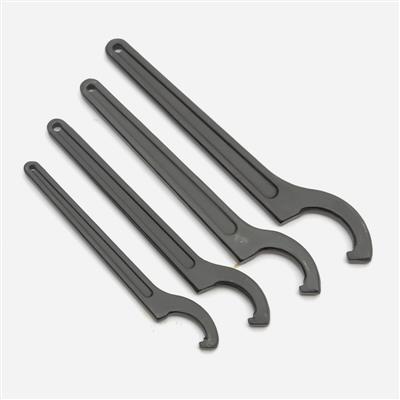
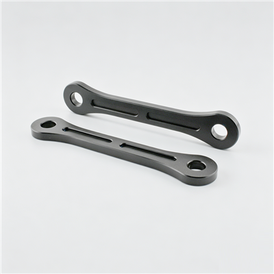
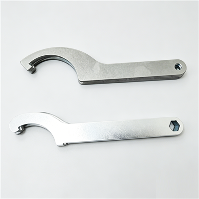
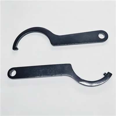
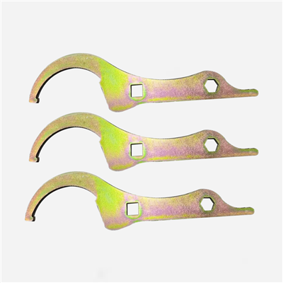
Process equipment such as wrenches and tooling is used in production, assembly, maintenance, or inspection processes. It is not assembled onto the final product and is considered process equipment. Its duties fall into three groups: assisting in installing or removing other parts, such as special wrenches and press-fit tooling, positioning or clamping workpieces to ensure machining or assembly accuracy, and inspecting specific dimensions or performance, such as go and no-go gauges and special inspection fixtures. Bonpora supports custom design from customer application scenarios, drawings or existing tool samples, and can optimise ergonomics and service life.
What separates a process tool that lasts a shift from one that lasts a decade is manufacturing control, and specifically heat treatment control. This guide describes the production route for tooling items, the process parameters that decide life and safety, and the inspection plan that keeps a batch consistent. It is written for tooling engineers and buyers who need to audit a supplier or write a specification that can actually be met.
Tooling begins with bar, plate or casting whose grade decides what the rest of the process can achieve. Chrome vanadium steel is the common choice for general hand tools because it carries good torque with reasonable toughness. Chrome molybdenum steel is used where shock loading is expected, such as impact sockets and heavy torque applications. Through-hardening tool steel is used for special wrenches, press tooling and gauges, where wear resistance at the working face is the main requirement and the hardness has to be controlled through the section.
Three checks belong at goods-in. Confirm the grade against the mill certificate and the marking on the bar, measure the section or diameter because an undersized bar cannot be recovered later, and record the heat number against the production batch. Where the tool will be used for inspection duty, the dimensional stability of the material matters as much as its hardness, so the certificate should be kept with the gauge record rather than filed only in purchasing.
Not every tool is made the same way. Matching the route to the shape and the volume keeps both cost and quality under control.
| Route | Typical items | Volume fit | Quality consideration |
|---|---|---|---|
| Closed die forging plus machining | Standard and heavy duty wrenches | Medium to high | Grain flow follows the shape, good fatigue behaviour |
| Machining from bar or plate | Special wrenches, low volume tooling, gauges | Low to medium | Full control of dimensions, material utilisation is lower |
| Laser cut and fabricated assembly | Checking fixtures, clamping frames | Low, frequently revised | Fixture accuracy and welding distortion must be managed |
| Casting plus machining | Complex bodies, handles, frames | Medium to high | Porosity control, machining allowance |
Where the working profile is unusual, electrical discharge machining or a profiling operation on a machining centre is used to generate the form after heat treatment or before final hardening, depending on the hardness required at the profile. The sequencing matters: a profile cut into soft material and then hardened may distort, while a profile cut after hardening needs a process that can handle high hardness.
Machining is where the failure-prevention features are created. The transition from the working end to the shank should carry a generous radius rather than a sharp internal corner, because that corner concentrates stress under every load cycle. Wall thickness at the load face should be held at or above the drawing minimum, since a few tenths of a millimetre removed to ease access can noticeably reduce torque capacity. Threaded or splined features should be machined in one setup where possible, so that concentricity is held by the machine rather than by the operator.
Surface condition also matters. A finish that is too rough becomes the initiation point for a fatigue crack under repeated load, and a finish that has been over-polished can hide a dimensional error. The drawing should state the finish and the areas where it applies, particularly at the working faces and at any fillet. Where a tool is assembled from more than one piece, the assembly operation belongs at this stage as well: press fits, pinned joints and retained inserts should be checked for seating before the tool goes to finishing, since a joint that has to be corrected afterwards will damage the coating.
Heat treatment is usually the difference between a tool that meets its specification and a tool that fails on the shop floor. Four parameters have to be controlled and recorded.
| Parameter | Why it matters | Control evidence |
|---|---|---|
| Austenitising temperature and time | Dissolves alloying elements and sets the as-quenched structure | Furnace chart or batch record |
| Quench medium and agitation | Controls cooling rate and therefore hardness and distortion | Quench record, batch hardness test |
| Tempering temperature and time | Trades some hardness for the toughness that prevents brittle failure | Chart plus hardness test after tempering |
| Atmosphere control | Prevents decarburisation and scale at the working face | Controlled atmosphere or protective packing record |
Decarburisation deserves special attention, because it removes carbon from the surface and leaves a soft skin over a hard core. The tool looks correct, passes a casual file test in the middle, and wears rapidly exactly where it should be hardest. If the furnace cannot be controlled, the process must include a machining allowance that is removed after heat treatment.
Distortion is the second risk. Long, thin tools and thin-walled sockets move during quenching, so the sequence should place the critical dimensions after hardening wherever the design allows, or include a straightening and checking step for tools such as long special wrenches. Straightening a hardened tool is possible within limits, and the limits should be written down rather than decided at the bench.
Finishing serves corrosion resistance, wear resistance and identification. Chrome plating on a hand tool reduces friction and resists corrosion but must be controlled for thickness and adhesion, since a flaking plate leaves sharp edges and a corrosion cell. Black oxide suits tools where a low reflectivity finish is preferred and a light oil film can be maintained. Shot blasting is often used to clean the surface and create a compressive layer before finishing, which is beneficial at the highly stressed areas.
For gauges and inspection fixtures, the finish requirement is different again: the working surfaces are usually ground and may be lapped, with sharp edges broken to a controlled radius. A gauge whose working face has a burr will give a false reading, and a gauge with a corroded face will wear quickly and lose its wear allowance.
A tool is inspected against its function, not only its dimensions. The plan below is a practical baseline for a series batch, and it should be extended for any item classified as inspection equipment.
| Characteristic | Method | First article | Running batch |
|---|---|---|---|
| Material grade | Certificate, in-house identification | Every heat | Certificate per heat |
| Critical dimensions | Calliper, micrometer, height gauge | Full layout | Sampled |
| Working end fit | Check against a master or a reference fastener | Every feature | Sampled |
| Hardness | Hardness test at the specified location | Every piece of the sample plus section check | Sampled per heat treatment batch |
| Surface finish and decarburisation | Visual, comparator, or metallographic where required | Per batch | Per heat treatment batch |
| Functional load test | Apply the working torque or force | Every piece of the sample | Sampled per batch |
| Coating or plating | Thickness gauge, adhesion test | Per finishing run | Per finishing run |
| Marking and identification | Visual, compare with the record | All pieces | Every piece |
For go and no-go gauges and checking fixtures, add two items: verification against the reference used to set the gauge, and the initial wear allowance measurement. Both values go on the gauge record so that later checks can show how fast the gauge is wearing.
A defect report is only useful if it identifies the process step that failed. The catalogue below links the visible defect to the likely cause and the action that prevents a repeat.
| Defect | Likely cause | Corrective action |
|---|---|---|
| Soft working face with a hard core | Decarburisation or inadequate atmosphere control | Restore atmosphere control, add a post heat treatment machining allowance |
| Hardness below specification after tempering | Furnace temperature error or excessive tempering time | Recalibrate the furnace, requalify the cycle |
| Crack at the head to shank transition | Sharp corner, quench stress or excessive hardness | Add a radius, review the quench and the tempering temperature |
| Distortion on a long tool | Quench orientation, uneven cooling | Revise the support fixture, add a controlled straightening step |
| Working end opened out beyond tolerance | Wear in service or an incorrect material grade | Confirm the grade, review the hardness specification |
| Plating blisters or flakes | Poor pre-treatment, contamination in the bath | Review the cleaning line, check bath chemistry, re-test adhesion |
| Burr left on a gauge working face | Deburr step skipped or tooling wear | Add deburr to the route and inspect before finishing |
A tooling batch should be traceable in the same way as a structural component. The minimum record links the batch or serial number marked on the tool to the material heat number, the heat treatment batch record with its hardness results, the finishing run, and the inspection results. For inspection equipment, add the verification against the reference, the wear allowance at issue, and the calibration interval.
Documentation has a commercial benefit as well as a quality one. When a customer reports that a special wrench deformed in service, the batch record answers whether the cause was a material substitution, a heat treatment deviation, or a genuine change in the torque applied. Without the record, the discussion is speculative, and speculation is expensive for both parties. This is the same traceability principle applied to components, and it is worth aligning the two systems so that the tooling record and the part record use the same batch coding convention.
It depends on the torque transmitted and whether the tool sees shock load. The specification should give a range with a defined check location rather than a single figure, because surface hardness and core hardness differ. The supplier should recommend the range once the fastener size and the working torque are known.
Check for decarburisation at the working face. A soft surface skin can be present even when a section hardness test passes, and it wears exactly where the tool does its work. Atmosphere control in the furnace, or a machining allowance removed after heat treatment, solves it.
Not always, but forging does orient the grain flow so that it follows the shape of the tool, which improves fatigue behaviour in a wrench that sees repeated load. For a special tool made in small quantity, machining from bar is normally the better economic choice and performs well.
Working surfaces are ground, and often lapped, with sharp edges broken to a controlled radius. The finish should be consistent so that wear is measurable, and any coating must not alter the working dimension. Verification against the reference and the initial wear allowance both belong on the gauge record.
Send the drawing or sample, the intended use, the torque or force involved and the expected usage rate. The factory will confirm the material, the forming route, the heat treatment specification and the inspection plan before production, and can deliver a prototype for trial where the application justifies it. Ergonomics and service life can be optimised as part of the design. Review the process tooling range, the selection and specification guide and the custom design guide, or reach the team through the contact page.