sales@bonporaparts.com
0086-10-64988621
English
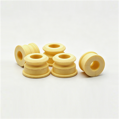
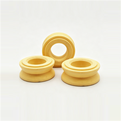
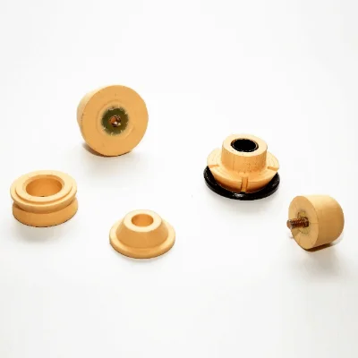
The buffer for cabin described in the Bonpora source row is an elastic component, typically made from high-elasticity polyurethane, installed between the truck cab and the chassis frame. Its function matches that of a jounce bumper, also called a bump stop, bump rubber, rubber buffer or strut bumper: it provides progressive auxiliary stiffness at the end of the compression stroke.
Replacing the part itself takes little time. Most of the working time goes into preparation, because the cab has to be supported safely, the mount has to be unloaded, and the seat has to be clean and undamaged before the new buffer is set in place. On an air suspended cab there is one extra step, since the mount must be isolated from the air spring before the cab is lifted.
The sequence below applies to a heavy-duty truck cab of the type listed in the source row, including Scania, MAN, DAF, Renault, Mercedes-Benz, BRG and Volvo. Always follow the workshop procedure for the specific model where one is available, and treat the arrangement here as the general method rather than as a substitute for it.
Collect everything before the cab is lifted. Working under a raised cab to fetch a tool is the most common cause of avoidable risk in this job.
| Category | Item | Why it is needed |
|---|---|---|
| Support | Rated jack and axle stands, or a cab support bar | Hold the cab at working height |
| Hand tools | Sockets and spanners for the mount fixings | Remove and refit the mount hardware |
| Lifting | Pry bar or lifting wedge | Open the gap without damaging the buffer |
| Cleaning | Brush, lint-free cloth, approved solvent | Clean the seat and contact faces |
| Measuring | Tape or gap gauge, torque wrench | Set ride height and clamp load |
| Inspection | Durometer, marker pen, camera | Record the condition of the removed part |
| Safety | Gloves, eye protection, chocks | Chock the wheels before lifting |
Two consumables are worth having on hand: a small quantity of the approved assembly lubricant, if the vehicle maker specifies one for the mount, and replacement fasteners where the original hardware is torque-to-yield or corroded.
Park on a level, hard surface, chock the wheels, apply the parking brake and switch off the engine. Allow the exhaust and engine compartment to cool if the buffer sits close to a hot component.
On an air suspended cab, release or isolate the air supply as specified for the model so the mount can be unloaded without fighting the air spring. If a height sensor or a levelling valve is fitted nearby, protect it from damage while the cab is raised.
Use the support points given by the vehicle maker. Lifting the cab on a floor pan or on a body panel will distort the structure, and the distortion may not be visible until the cab is lowered again.
Photograph the mount before anything is removed and mark any cam washer, shim or spacer so that it goes back in the same position. Geometry changes here are difficult to detect afterwards.
Work on one mount at a time unless the vehicle maker allows otherwise, so the cab keeps its remaining supports.
Keep the removed buffer for the vehicle record. The condition of the old part is the clearest evidence of why the replacement was needed, and it supports any later discussion of the warranty terms quoted in the source row, typically 1 to 2 years or 50,000 to 100,000 km.
The new buffer will only reach its stated performance if the surfaces it works against are correct. Four checks cover most faults.
| Check | Acceptance | Action if it fails |
|---|---|---|
| Cleanliness of the seat | No rust scale, old bonding material or debris | Clean and re-inspect |
| Flatness of the contact face | No local crushing or a raised burr | Dress or replace the plate |
| Condition of the bracket | No cracks, no elongated fixing holes | Repair or replace before fitting |
| Free movement of the mount | No seized pivot or binding sleeve | Free or replace the seized part |
Fitting a new buffer onto a worn or distorted seat is the most common reason a fresh part appears to fail quickly.
Seat the buffer fully into its sleeve or cup, checking that it sits square and that any locating tab or flat aligns with its keyway. A buffer that is not seated square will show uneven wear within a short distance.
Refit any shim, cam washer or spacer in the position recorded during removal. On an air suspended cab, make sure the buffer is located so that it meets its stop at the designed gap rather than being pre-loaded.
Start every fastener by hand and run it down until it is just touching. This step reveals cross threading and confirms that all the parts of the stack are present.
Lower the cab onto its mounts and restore the air supply where applicable. Let the cab settle to its normal ride height, then check the gap between the buffer and its contact face. Correct the height if the reading is outside the model specification.
Tighten the fixings in the sequence given for the model, in two stages. Where no figure is published, record the value used so that the next service on the same vehicle starts from a known baseline.
Confirm that pipes, wiring and air lines are clear of the mount through the full range of cab movement and that nothing is trapped between the buffer and its stop.
The figures below describe what to measure and record. Values themselves vary by model and by fastener size, so use the vehicle maker data where it exists and record what was actually applied.
| Item | What to do | Record |
|---|---|---|
| Cab support point | Use the maker points only | Not applicable |
| Ride height gap | Measure with the cab at normal height | Left and right reading |
| Fixing torque | Tighten in the published sequence, two stages | Value applied and the wrench used |
| Sleeve or bond condition | Check that the buffer does not rotate by hand | Pass or fail |
| Re-check after the first run | Inspect fixings and gap after a loaded trip | Any change from the initial reading |
| Error | Symptom afterwards | Correction |
|---|---|---|
| Dirt or old bonding material left in the seat | Uneven wear, part sits high | Remove, clean, refit |
| Spacer or cam washer omitted | Wrong ride height, early contact | Refit the missing item |
| Air spring not recharged before torque | Buffer pre-loaded, harsher ride | Set height then re-torque |
| Cab lifted on a body panel | Distorted floor, poor door fit | Inspect and repair the structure |
| Fixings left at the unloaded torque | Loose mount, knocking | Re-torque in the correct sequence |
| Only one side replaced | Cab sits unevenly, one side bottoms first | Pair the buffers |
The front pair usually carries the larger share of the vertical load, so the support and the ride height measurement should be taken on both sides before anything is released. Check the metal cup or sleeve carefully, because corrosion here is common on vehicles that work in a wet climate.
The rear of a tilting cab combines the buffer with a pivot or a stabiliser element. In this position the buffer is also asked to resist longitudinal rocking, so the pivot must move freely before the new part is fitted and the guide surfaces should be checked for wear.
On a mechanical cab suspension the buffer is part of the primary load path and the gap at ride height has a direct effect on ride quality. Measure both sides and record the numbers as a baseline.
On an air suspended cab the air spring carries the static load and the buffer works mainly as an end-stop. Isolate the air supply, set the ride height, then torque, and confirm that the levelling valve or height sensor has not been disturbed.
Before the truck returns to service, confirm that the gap is even on both sides of the cab, that all fixings are at their final torque, and that nothing has been trapped or left loose. Then arrange a re-check after the first loaded trip: a new polyurethane buffer settles slightly under its first full compression, which can reduce the clamping load on the fixings. Re-check the gap and the torque, top up the air system if applicable, and close the job with the recorded values in the vehicle file.
The source row states a design life of not less than 80,000 km or two years under normal use, with no cracking, no excessive permanent deformation and no stiffness loss. Recording the fitting mileage at installation is what makes it possible to judge that figure later on your own fleet data.
The buffer itself is a quick replacement, but the job should be estimated around the cab support and the mount preparation rather than around the part. On an air suspended cab, allow extra time for isolating the air supply and resetting ride height.
It is the better practice. Two buffers of different age have different stiffness, so the cab sits unevenly and one side reaches its stop before the other.
Only where the model procedure allows it and where the mount can be unloaded safely. On most heavy-duty cabs the mount has to be unloaded, so the cab must be supported on rated equipment.
The date and mileage, the part number and compound, the gap measurement on both sides, the torque applied, and a photograph of the removed part. Those five items make the next service decision much simpler.
Bonpora Parts and Components supplies cabin buffers and cab mount components for Scania, MAN, DAF, Renault, Mercedes-Benz, BRG and Volvo trucks, and produces custom polyurethane parts to drawing or sample. Begin with the commercial vehicle range, read the cabin buffer selection guide or the cabin buffer failure analysis, and compare the polyurethane bump stop range. Related content sits under chassis and suspension components, and the contact page reaches the engineering desk directly.