sales@bonporaparts.com
0086-10-64988621
English
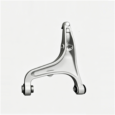
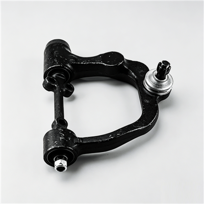
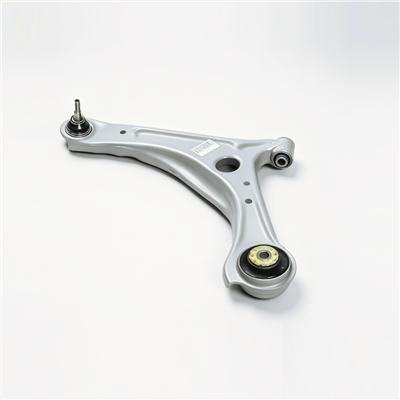
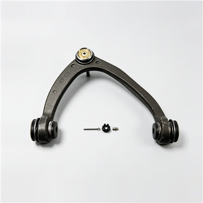
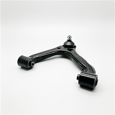
A control arm, also written as A-arm, A-frame, suspension arm, trailing arm or track control arm, is a guiding component of the suspension system. One end is connected to the subframe or the body through a bushing, and the other end is connected to the knuckle through a ball joint. It transmits longitudinal and lateral forces between the wheel and the vehicle body, it controls the path of wheel motion and maintains alignment parameters such as camber and toe, and it withstands the loads generated during braking, acceleration and cornering. Bonpora builds the part as a stamped steel plate welded structure, a forged aluminium alloy part or a cast iron part, states compliance with IATF 16949, lists critical inspection as dimensional accuracy of the mounting points, welding strength, ball joint starting torque and fatigue life, and gives a warranty of two years or 50,000 km for cast and welded parts. This article takes the next step for a workshop or a fleet: how these arms actually fail, how a worn one is separated from a noisy one, and when the correct answer is a bushing, a ball joint or the complete arm.
Diagnosis goes wrong when the arm is treated as a single object. In practice it is a beam plus two interfaces, and the interfaces wear on a completely different timescale from the beam.
A correctly specified beam has a fatigue life far longer than the elastomer or the ball joint inside it. Where fatigue cracking does appear in the field, the usual reasons are an impact that started a crack, corrosion that reduced the section, or a load case the arm was never specified for, such as a lifted or heavily loaded vehicle still on a standard arm.
The bushing and the ball joint both contain moving surfaces under load. Rubber ages, an elastomer takes a set, a boot splits, grease washes out and a bearing surface wears. When one of those happens the driver notices it as a noise, a wander at speed or irregular tyre wear, and the workshop is asked to decide whether the arm is at fault.
The list below is the practical set for a road vehicle, ordered roughly by how often each one is the real cause of a complaint.
Rubber bushings crack with age and ozone exposure, then lose stiffness and allow the arm to move further than the design intended. A polyurethane or engineering elastomer bushing can also wear at the bore if the fit was loose or if the surface was damaged during fitting. Symptoms include a dull knock over small bumps, a change in steering feel and alignment values that move between checks.
Starting torque is the number to watch. A joint that has lost preload will move too freely, which shows up as a clunk on direction change, as play felt with the wheel lifted, or as a reading below the target window. A split boot accelerates the process because water and grit reach the bearing surface. A joint that feels unusually stiff should also be questioned, since high preload wears the bearing surface faster.
Road salt attacks the coating first and the base material second. On a stamped and welded arm the areas to inspect are the weld toes, the inside of the closed section if it is open, and the edges of the flanges, since these are where coating coverage is thinnest. Aluminium arms do not rust in the same way, but they can suffer from galvanic attack where steel fasteners or inserts meet the alloy.
Fatigue cracks start at a stress raiser: a weld toe, a stamped rib end, a sharp change of section or an earlier impact mark. They usually appear on the loaded face of the arm rather than on the neutral axis. A crack that is visible after cleaning is a replacement, not a repair, and the cause should be looked for in the rest of the assembly.
A kerb strike or a pothole impact bends the arm and moves the alignment values. A bent arm is often reported first as a steering pull or as a tyre wearing on one edge. Comparison against a known-good arm or against the alignment data is more reliable than a visual judgement on the vehicle.
Welds can crack at the toe of the joint, and a bushing can lose its press fit in the bore and begin to walk out. Both are assembly and quality issues rather than wear, and both call for the complete arm rather than a workshop repair.
| Symptom reported | Likely location | How to confirm | Action |
|---|---|---|---|
| Dull knock over small bumps | Bushing end | Pry test with the vehicle lifted, inspect the elastomer for cracks | Bushing or complete arm, depending on bore condition |
| Clunk on direction change | Ball joint | Play check with the wheel lifted, compare starting torque | Complete arm where the joint is not serviceable |
| Steering wander at speed | Bushing end or alignment | Alignment reading repeated after a short drive | Fix the interface first, then re-check the geometry |
| One tyre edge wearing fast | Arm geometry or impact damage | Compare alignment values and inspect for deformation | Replace the arm, then reset the alignment |
| Rust staining or blistering | Weld toe or coating edge | Clean the area and examine the section | Replace if the section is reduced |
| Visible crack after cleaning | Weld toe or rib end | Dye penetrant or a close visual check | Replace without repair |
A short, repeatable sequence keeps the diagnosis honest and stops parts being changed on suspicion.
First, confirm the complaint under the conditions the driver described, because a knock over bumps and a knock on turning often have different causes. Second, lift the vehicle and support it safely, then inspect the boots, the coating and the weld areas before applying any force. Third, apply a controlled pry load at the bushing end and watch for movement that does not belong to the elastomer. Fourth, check the ball joint for play and for a starting torque reading in the stated window. Fifth, repeat the alignment reading and compare it with the previous service record.
Many complaints attributed to the arm come from the damper, the top mount or the stabiliser link. The two checks that separate them are the pry test at the bushing end and the alignment reading: an arm that has moved its geometry will change the alignment, while a worn damper usually will not. When both are worn at the same time, as happens on a high mileage front axle, replacing one and leaving the other gives the driver a return visit.
Measurement on the bench converts an opinion into a decision, and it also protects the workshop if the complaint returns.
Compare the mounting point coordinates with the drawing where one exists, or against a known-good arm of the same part number. Check the bore diameter for the bushing at two axes, since an oval bore explains a bushing that moves. Measure the ball joint starting torque in the stated window and at the stated temperature. Where a scan or a comparison fixture is available, an overall shape check settles the deformation question quickly.
A single out-of-range value rarely tells the whole story. A bore that is oval plus a bushing that has walked suggests the press fit was lost and the assembly was running with movement. A crack at a weld toe plus coating damage suggests corrosion assisted fatigue. Reading the values as a set is what turns a measurement sheet into a repair decision.
| Measurement | What a deviation indicates | Decision it supports |
|---|---|---|
| Mounting point coordinates | Bent or incorrectly manufactured arm | Replace, and confirm the cause of the impact |
| Bushing bore diameter, two axes | Oval bore or damaged surface from a previous press | Replace the arm rather than re-press a bushing |
| Ball joint starting torque | Low preload or a damaged bearing surface | Replace the arm where the joint is not serviceable |
| Play at the bushing end under pry load | Elastomer takes a set or the press fit is lost | Bushing or arm, based on the bore result |
| Alignment values after a short drive | Geometry moving under load | Confirm the failing interface before adjustment |
The cheapest decision is not always a bushing, and it is not always a complete arm.
A bushing change is appropriate when the arm itself is sound: the bore is round and undamaged, the mounting points are within the drawing tolerance, the coating is intact and the ball joint is inside its torque window. In that case the bushing is the wear item and replacing it restores the intended stiffness.
The complete arm is the correct answer when the ball joint is not serviceable, when the bore has lost its press fit, when there is any crack, when the section is reduced by corrosion, or when the geometry is outside tolerance after an impact. Re-pressing a bushing into a damaged bore produces an assembly that will move again, and welding a cracked arm is not a repair that belongs on a road vehicle.
| Condition found | Recommended action | Reason |
|---|---|---|
| Elastomer cracked, bore round within tolerance | Replace the bushing | The arm retains its geometry and stiffness |
| Ball joint outside the starting torque window | Replace the complete arm | Preload and bearing surface cannot be restored in service |
| Bore oval or damaged, bushing has walked | Replace the complete arm | A new bushing cannot hold the intended fit |
| Crack at weld toe or rib end | Replace the complete arm | A cracked structural part is not a repair item |
| Coating broken with section loss | Replace the complete arm | Remaining fatigue life is unknown |
| Geometry outside tolerance after impact | Replace the complete arm | Alignment cannot be recovered by adjustment |
Tyres often report an arm problem before the driver does. Wear concentrated on one shoulder, a feathering pattern across the tread, or a steering wheel that sits off centre after a straight run all point to geometry that has moved. Because the arm sets camber and toe, a change in those values between services is a strong indicator that a bushing has softened or that an impact has moved a mounting point. Recording the alignment values at every service makes the trend visible, and it is far cheaper than waiting for a tyre to fail.
Most premature arm failures are caused by something outside the arm. Impact damage follows kerbs, potholes and off-road use; corrosion follows salt exposure without underbody cleaning; interface wear accelerates when unmatched bushings or ball joints are fitted, or when fasteners are tightened with the suspension at full droop instead of at ride height. Specifying the matching bushing and ball joint with the arm, checking torque at ride height, and cleaning the underside after winter are the practical measures that extend the interval. Where a vehicle works on poor roads, the inspection interval should be shortened rather than the part changed for a heavier one without reviewing the rest of the layout.
Yes. The arm sets camber and toe, so once a bushing softens or a mounting point moves, the tyre runs at the wrong angle and wears on one edge. The wear will usually return after an alignment adjustment unless the worn interface is replaced.
No. Stabiliser links, damper top mounts and worn dampers produce similar noises. A controlled pry test at the bushing end and a repeat alignment check are what separate the arm from the other components.
Where both arms have covered the same distance and the same conditions, replacing them together keeps the axle behaviour symmetrical and avoids a second visit. If only one side has impact damage, the decision can be made on the measured condition of the other.
Bonpora gives two years or 50,000 km for cast and welded parts. Keep the installation record, since the warranty normally depends on the arm being fitted with matching interfaces and at the correct ride height.
Send the vehicle details, the part number and the measurements taken during diagnosis to the technical team at Bonpora Parts and Components Co.,Ltd. for help in separating a worn interface from a damaged arm. The control arm range covers the selection and specification guide for a new programme, and matching mounting bushes are supplied with the arm.