sales@bonporaparts.com
0086-10-64988621
English
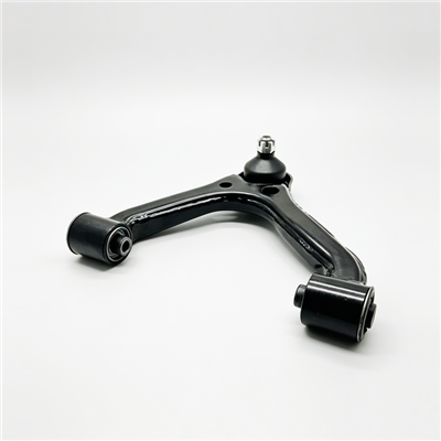
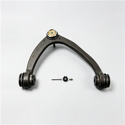
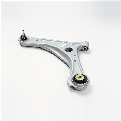
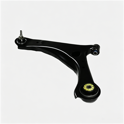
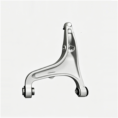
A control arm, also written as A-arm, A-frame, suspension arm, trailing arm or track control arm, is a guiding component of the suspension system. One end is connected to the subframe or the body through a bushing, and the other end is connected to the knuckle through a ball joint. It transmits longitudinal and lateral forces between the wheel and the vehicle body, controls the path of wheel motion and maintains alignment parameters such as camber and toe, and it withstands the loads generated during braking, acceleration and cornering. Bonpora produces the part as a stamped steel plate welded structure, a forged aluminium alloy part or a cast iron part, states compliance with IATF 16949, and defines critical inspection as dimensional accuracy of the mounting points, welding strength, ball joint starting torque and fatigue life, with a warranty of two years or 50,000 km for cast and welded parts. Assembly of the matching bushings and ball joints is part of the same flow. This article looks at how the part is actually made and controlled, which is the information a buyer needs when auditing a supplier or reading a control plan.
A control arm cannot have one generic control plan, because the process that creates the risk is different in each route.
A stamped and welded arm carries its risk in the weld and in the dimension that survives welding. A forged arm carries its risk in the grain flow, the heat treatment and the machined seat for the ball joint. A cast arm carries its risk in the solidification and in the soundness of the sections that will be machined. The control plan should be written against those specific risks rather than copied between routes.
Whatever the route, the four items named for this part apply: dimensional accuracy of the mounting points, welding strength, ball joint starting torque and fatigue life. Welding strength is not applicable to a forged or a cast arm without a weld, but the other three are universal, and they connect the incoming material, the forming stage, the machining stage and the final assembly stage into one measurable chain.
Every route begins with a material that has to be verified against the drawing before it enters the process.
Check the grade, the thickness and the mechanical properties against the material certificate, and confirm the coil or sheet identity against the batch record. Thickness variation matters more than it appears, because the forming press is set to a nominal blank and a coil at the low end of the tolerance range can change the shape that comes out of the die.
Billet or bar stock should be verified by grade and by traceability, since the alloy and its temper decide both the forgeability and the final strength after ageing. Surface condition also matters: a billet with deep surface defects can carry those defects into the forging.
Cast iron quality depends on the melt. Charge composition, inoculation and pouring temperature are the variables that decide whether the casting comes out with the intended graphite structure and without hard spots that will damage a machining tool. Records of the melt should be kept against the casting batch.
| Route | Main process risk | Control focus | Evidence to keep |
|---|---|---|---|
| Stamped steel, welded | Weld quality and post-weld distortion | Weld parameters, fixture control, dimension after welding | Material certificate, weld record, dimensional report |
| Forged aluminium | Grain flow and heat treatment | Billet heating, die condition, ageing cycle | Billet certificate, heat treatment record, hardness results |
| Cast iron | Solidification defects and section soundness | Melt control, gating, machining allowance | Melt record, casting inspection, machining report |
The stamped and welded route is the most common for passenger car arms, and its quality is decided by the die, the weld and the fixture that holds the parts while they are joined.
The blank is cut from coil, formed in a press, and trimmed or pierced. Springback is the recurring problem in forming a closed or partly closed section, because the material returns part of its bending angle as the tool releases. The usual controls are a compensated die, a restrike station and a first-off dimension check on every tool change. The check should be taken on the formed part, not on the tool, because the tool does not include the material behaviour.
Shells are joined by projection, spot, seam or arc welding depending on the design. Heat input distorts the assembly, so the sequence and the cooling pattern are part of the specification rather than something the operator decides. Weld parameters such as current, time and pressure or wire feed should be recorded and monitored, and the fixture should be verified at a stated interval, because a worn locator moves the mounting points even when every weld is perfect.
After welding, the mounting points and the interface locations are measured against the drawing. This is the inspection that protects the alignment of the finished vehicle, and it is the reason the mounting points appear first in the critical list for this part. Where a dimension is drifting, the cause is usually the fixture or the weld sequence rather than the die.
Forging produces a continuous grain flow around the loaded sections, which is why it supports a lighter arm for the same duty.
Billet temperature and die temperature decide whether the material fills the die and whether the grain flow follows the intended direction. A cold billet or a worn die produces a part that passes a visual check and fails a fatigue check. Die condition should therefore be monitored against a defined service interval, not only replaced when a defect appears.
After forging, the flash is trimmed and the part receives the heat treatment or ageing cycle specified for the alloy. For an aluminium forging, solution treatment and artificial ageing set the final mechanical properties, so the furnace cycle and its records are a key control point. Hardness checks on the finished part are a practical confirmation that the cycle was applied.
The ball joint seat and the bushing bore are machined after forging. Tolerance, surface finish and position relative to the mounting points are all critical, because the seat decides the clamp load on the stud and the bore decides whether the bushing holds its fit. Machining fixtures should be located from the same datum used for the dimension report, so that the measurement and the machining agree.
Cast iron allows ribbed sections that put material exactly where the bending loads are highest.
The pattern and the gating system decide how the metal fills the mould and how it solidifies. Shrinkage porosity, cold shuts and sand inclusions are the classic defects, and they tend to appear in heavy sections, at rib junctions and at the last points to solidify. Good practice places the gating so that the heavy sections feed correctly, and inspects the first castings of a run before production continues.
Machining allowance must be enough to clean up the casting after any distortion, but not so much that the section becomes thin. Before machining, the casting is normally checked visually for surface defects and, on critical parts, by a method that detects internal porosity. After machining, the bore and the ball joint seat are measured against the drawing in the same way as a forged arm.
These four items are the spine of the control plan, and each one answers a different question about the finished part.
Mounting point dimensions confirm that the part will place the wheel where the alignment data expects it. Weld strength confirms that a welded assembly can carry the loads that pass through its joints, and it is normally verified by parameter control plus destructive section samples or peel tests at a stated frequency rather than by checking every part. Ball joint starting torque confirms that the joint was assembled with the intended preload, and it is measured at a stated temperature because the value moves with temperature. Fatigue life confirms that the design survives repeated cycles, and it is demonstrated on a sample of the design rather than on each unit.
An inspection plan for this part normally has a first-off check at every setup change, in-process checks at a stated frequency, and a final inspection with a dimension report per batch. Torque values for the assembled joint are recorded per batch or per shift depending on volume, and the fatigue test report is kept with the design file rather than with the production batch.
| Inspection item | Stage | Frequency | Record |
|---|---|---|---|
| Material grade and properties | Incoming | Per heat or batch | Material certificate |
| Formed or forged shape | After forming | First off and at setup change | First article dimension sheet |
| Weld parameters and quality | Welding | Continuous monitoring, samples at stated frequency | Weld record and sample result |
| Mounting point dimensions | After joining or machining | First off, in process, final | Dimensional report |
| Ball joint starting torque | Assembly | Per batch or per shift | Torque record at stated temperature |
| Fatigue life | Design validation | On design approval or on change | Fatigue test report |
| Coating thickness | Final | Per batch | Coating record |
The arm is only as good as the interfaces fitted to it, and matching bushings and ball joints are supplied with the part for that reason.
The bushing is pressed into a bore that must be round, clean and within tolerance. A bore that is oval or scored will not hold the intended interference, and the bushing will move once the vehicle is in service. Insertion force and depth should be monitored, because a sudden change in insertion force usually indicates a bore problem rather than a bushing problem.
For the ball joint, the correct grease quantity, a correctly seated and untwisted boot and a measured starting torque are the three controls that matter. The boot is the only seal protecting the bearing surface, so a boot that is pinched during assembly shortens the life of the joint before the vehicle is delivered. The starting torque is then measured and recorded against the stated window.
A structural part on the underside of a vehicle lives in salt, water and grit, so the coating is a functional specification rather than a finish.
Coating systems are chosen against the corrosion requirement of the market, and the requirement is normally tested with a salt spray exposure. Where an aluminium arm is used alongside steel fasteners or inserts, the coating and the isolation between the two materials matter as much as the steel coating does on a stamped arm.
Coating damage happens at handling, at the press, at the weld fixture and at packaging. Points that touch the part should be free of burrs and chips, and the parts should not be stacked on bare metal surfaces after coating. Where a small repair is permitted, it should be defined in the specification rather than decided at the shipping area.
Traceability turns a field question into an answer, and packaging decides whether the part arrives in the condition it was inspected in.
Each arm should carry a marking that ties it to the part number and the production batch, and the batch should link back to the material, the weld or casting record, the dimension report and the torque record. With that chain in place, a claim within the two year or 50,000 km warranty period can be assessed on evidence rather than on opinion.
The ball joint stud, its thread and its boot are the most vulnerable features, so they need protection from any load in transit. Arms should be separated so that coating does not rub between them, and cartons should state the part number, the quantity and the batch. Loose bulk packing on a coated suspension arm trades a small saving for corrosion that starts before the part reaches the shelf.
| Defect | Route where it occurs | Root cause to check | Correction |
|---|---|---|---|
| Mounting point out of tolerance | Stamping, forging or casting | Worn fixture, die condition, machining datum | Re-set the fixture, verify the datum, quarantine the batch |
| Weld porosity or short weld | Welded assembly | Parameters, surface cleanliness, electrode condition | Re-set parameters, inspect samples, retrain the station |
| Bushing moves after pressing | Assembly | Bore roundness, insertion depth, interference | Re-check the bore, review the press setup |
| Starting torque outside window | Assembly | Preload setting, grease quantity, temperature of measurement | Re-set preload, confirm the measurement method |
| Coating thin or damaged | Final finish and handling | Line parameters, contact points, stacking | Repair or rework per the specification, revise handling |
Because it is verified by process control plus sampling rather than by an inspection on each unit. Weld parameters are monitored continuously, and section or peel samples at a stated frequency confirm that the parameters produce a sound joint.
On a sample of the design, against a defined load case, and the report is kept with the design file. It is a design validation rather than a production check, and it is normally repeated when the design, the material or the process changes.
It proves that the joint was assembled with the intended preload and that the internal bearing surface is in the expected condition. The value is temperature sensitive, so the measurement method and the temperature belong in the specification.
It depends on the shape and the volume. Forging and casting carry significant tooling cost that has to be amortised over the quantity, while a stamped and welded arm can sometimes be produced from simpler tooling. Sharing the annual volume with the supplier is what allows a realistic recommendation.
Send the drawing, the load case and the expected volume to the technical team at Bonpora Parts and Components Co.,Ltd. to discuss which route suits the programme and what the control plan will contain. The control arm range lists the available construction routes, the selection and specification guide covers the drawing data, the wholesale guide explains how to compare quotations on equal content, and the custom development service supports drawing and scan based projects.