sales@bonporaparts.com
0086-10-64988621
English
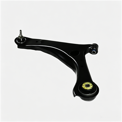
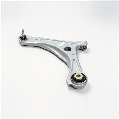
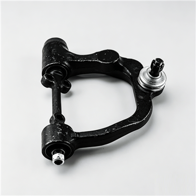
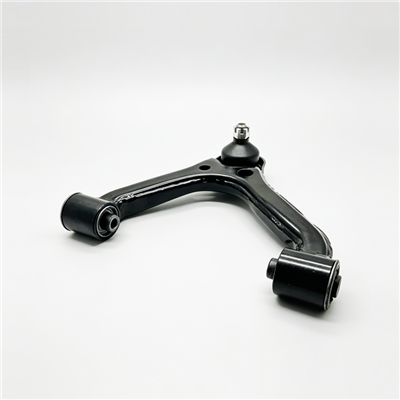
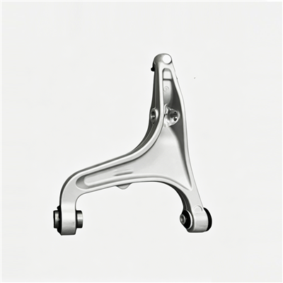
A control arm, also written as A-arm, A-frame, suspension arm, trailing arm or track control arm, is a guiding component of the suspension system. One end is connected to the subframe or the body through a bushing, and the other end is connected to the knuckle through a ball joint. Bonpora lists three duties for the part. It transmits longitudinal and lateral forces between the wheel and the vehicle body, it controls the path of wheel motion and holds the alignment parameters such as camber and toe, and it withstands the loads generated during braking, acceleration and cornering. The material routes offered are stamped steel plate welded structure, forged aluminium alloy and cast iron. Quality is stated against IATF 16949, with critical inspection covering dimensional accuracy of the mounting points, welding strength, ball joint starting torque and fatigue life, and the warranty for cast and welded parts is given as two years or 50,000 km. Development is supported from customer drawings or scanned data, with different material options, lightweight design solutions and matching ball joints and bushings. This guide translates those points into the specification data a purchasing team needs when it orders a suspension arm.
The control arm is a link, not a spring and not a damper. It decides where the wheel can go, while the spring and the damper decide how fast and how far it moves. That separation is useful when the arm is specified, because it means the arm is judged on geometry, stiffness and durability rather than on ride comfort.
Longitudinal loads arrive during braking and acceleration, lateral loads arrive during cornering, and vertical loads travel through the arm whenever the wheel moves. The arm carries all three and passes them into the subframe or the body through the bushing end, and into the knuckle through the ball joint. Where the arm sits in the layout decides the share of each load it sees, which is why the same drawing cannot be swapped between a front lower position and a rear trailing position without reviewing the numbers.
The mounting position of the arm sets the static camber and toe, and the length and the pivot axis set how those values change as the wheel travels. A millimetre of error at a mounting point moves the alignment reading, which is why the queue data names dimensional accuracy of the mounting points first among the critical inspection items. A buyer who supplies the vehicle model, the position in the layout and the alignment targets gives the supplier enough information to confirm the geometry before any tooling is committed.
Stamped steel plate welded structure, forged aluminium alloy and cast iron all appear in the same catalogue, and each route changes mass, stiffness, tooling cost and repair practice.
Two or more stamped shells are welded into a closed or partly closed section. The route is common for high volume passenger car arms because tooling cost falls quickly with volume, and because the welded box gives good stiffness in the directions that matter. The critical variables are the steel grade and thickness, the weld length and penetration, the position of the mounting points after welding, and the corrosion protection of the internal surfaces.
Forging produces a continuous grain flow around the loaded sections, which allows a lighter arm for the same duty. The trade-off is tooling cost and a design that must respect the forgeable shape, so forged arms suit performance and lightweight programmes where the mass saving justifies the investment. Surface treatment and any insert for the ball joint need to be defined at the design stage rather than added later.
Cast iron offers high stiffness and good damping, and it tolerates the ribbed shapes that place material exactly where bending loads are highest. Its mass is the obvious penalty. Where a cast arm is specified, the drawing should state the grade, the section thickness limits and the machining allowance at the ball joint seat and the bushing bore.
| Construction | Typical duty | Mass | Points to write into the drawing |
|---|---|---|---|
| Stamped steel, welded shells | High volume passenger car arms | Medium | Steel grade and thickness, weld length and penetration, post-weld dimension control, internal corrosion protection |
| Forged aluminium alloy | Lightweight and performance programmes | Lowest | Alloy grade, grain flow direction, insert for ball joint, surface treatment, hardness after ageing |
| Cast iron | Stiffness and damping priority | Highest | Grade, section thickness, rib layout, machining allowance at bore and ball joint seat |
An arm rarely fails in its middle. Most service problems start at the bushing end or the ball joint end, because those are the parts that move and wear.
The bushing carries the arm to the subframe and allows rotation and a limited amount of deflection. Rubber bushings are quiet and cheap but add stiffness in directions that affect ride and handling, while polyurethane and other engineering elastomers allow a different stiffness balance. The specification line that matters is the bore diameter plus its tolerance, the surface finish inside the bore and the axial retention method, because a bushing pressed into an out-of-round bore will not hold its intended stiffness. Matching bushings are available with the arm, which removes the risk of a fit that is close but not correct.
Starting torque, also described as breakaway torque, measures how much effort is needed to move the ball stud out of rest. It is a direct indicator of the preload and the condition of the bearing surface inside the joint. A value that is too low suggests the joint may feel loose and generate noise, while a value that is too high points to excessive preload and faster wear. This is why starting torque appears in the critical inspection list. The arm drawing should state the target window, the test method and the ambient temperature used for the measurement.
Development is accepted from customer drawings or scanned data, with material options and lightweight design solutions offered and matching ball joints and bushings supplied. The clearer the input, the shorter the confirmation loop.
Vehicle model, position in the layout, left or right hand, and the OE reference if one exists. Then the geometry: mounting point coordinates and tolerances, arm length, pivot axis, and the ball joint taper or thread. Then the duty: design load, alignment targets and the intended service interval. Finally the interfaces, meaning the bushing bore and the ball joint specification, plus any coating or marking requirement.
Where no drawing exists, a scan of the original arm is a practical starting point. A scan captures the shape, but it does not capture the material grade, the weld specification or the heat treatment, so those have to be agreed separately. The usual sequence is to compare the scanned geometry with the known alignment data for the vehicle, confirm the material and the ball joint, and then produce a first article for fitment trial.
| Drawing value | Why it is needed | Typical method of confirmation |
|---|---|---|
| Mounting point coordinates and tolerance | Sets camber, toe and wheel position | Coordinate measurement on the first article |
| Ball joint seat taper or thread | Decides stud engagement and clamp load | Gauge check plus assembly trial |
| Ball joint starting torque window | Indicates preload and internal bearing condition | Torque measurement at the stated temperature |
| Bushing bore diameter and finish | Decides retention and rotational stiffness | Bore gauge and surface comparison sample |
| Steel grade, alloy grade or cast grade | Sets strength, fatigue behaviour and mass | Material certificate against the drawing |
| Weld length and penetration | Decides the strength of a stamped welded arm | Weld inspection record and section sample |
| Coating or surface treatment | Decides corrosion life in road salt conditions | Coating thickness and salt spray record |
Bonpora states that quality complies with IATF 16949 and that critical inspection covers the dimensional accuracy of mounting points, welding strength, ball joint starting torque and fatigue life. Those four items are worth understanding individually, because each answers a different question.
Dimension checks on the mounting points prove that the arm will place the wheel where the alignment data expects it. Weld strength checks prove that a stamped and welded arm can carry the loads that pass through its joints. Starting torque proves that the ball joint was assembled with the intended preload. Fatigue testing proves that the arm survives repeated load cycles rather than only a single overload. Together they cover geometry, joint integrity, interface condition and durability.
Ask for the dimension record, the weld inspection record, the starting torque record and the fatigue test report, plus the material certificates and the coating record where applicable. Keeping the records with the batch makes a later field question traceable, and it allows a fleet or a workshop to compare an incoming arm against the data set used at approval.
For cast and welded parts Bonpora gives a warranty of two years or 50,000 km. That figure is a useful anchor for a service plan, but it should be read together with the duty of the vehicle. A light passenger car on sealed roads and a loaded commercial vehicle on broken surfaces place very different demands on the same arm, so the maintenance interval should follow the application rather than the warranty period alone.
Lightweighting works when material is removed from the low-stress areas and kept around the load paths. A forged aluminium arm, a thinner stamped shell with a revised rib layout or a redesigned cast section would all be evaluated on stiffness, strength and fatigue life rather than mass alone. The buyer who supplies the load case and the alignment targets makes that evaluation possible. Where mass is reduced, the ball joint and bushing specification should be reviewed at the same time, since a change of arm stiffness shifts the load that reaches those interfaces.
Most rejected arms are technically well made and simply do not match the application. The table below lists the errors that appear most often at the incoming inspection bench.
Confirm the position and the hand, compare the ball joint seat rather than only the overall length, check that the bushing supplied is the one specified, and read the alignment data before the arm is fitted. A single five minute comparison against the removed part avoids most of the return traffic.
| Mistake | Consequence | Prevention |
|---|---|---|
| Wrong position or wrong hand ordered | Will not fit, or fits with incorrect geometry | Confirm layout position and left or right hand on the order |
| Ball joint seat matched by appearance | Stud engagement or clamp load incorrect | Gauge the taper or thread against the drawing |
| Bushing omitted or substituted | Stiffness and alignment behaviour change | Order the matching bushing with the arm |
| Material grade not verified | Fatigue life below the design intent | Request the material certificate with the batch |
| Alignment data assumed from the old part | Wear pattern carried into the new assembly | Verify against the vehicle alignment specification |
The terms overlap. Wishbone usually describes a forked arm, while control arm is the wider name that also covers trailing and track control arms. The deciding factor is the layout position and the mounting arrangement, not the name on the catalogue page.
It indicates the preload and internal condition of the joint at the moment of assembly. A value outside the stated window points to a joint that may run loose or wear early, so it is a useful incoming inspection item rather than a workshop measurement.
It can, but ordering the matching interfaces with the arm removes a fit risk. Bonpora supplies matching ball joints and bushings, and where the arm is developed from a drawing the interfaces are normally confirmed together with the geometry.
Bonpora gives two years or 50,000 km for cast and welded parts. Real service life depends on road conditions and load, so the practical approach is to inspect the bushing and ball joint at the regular service interval and to judge the arm on measured play rather than on age alone.
A drawing, a scan or a complete vehicle description is enough to start a review of geometry, material and interfaces. Send the data to the technical team at Bonpora Parts and Components Co.,Ltd., or browse the control arm range and the custom development service that supports drawing and scan based projects. The related mounting bushes and the wider chassis and suspension programme cover the interfaces that work with this arm.