sales@bonporaparts.com
0086-10-64988621
English
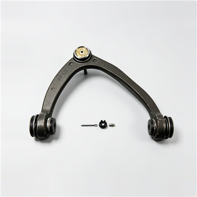
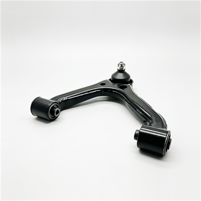
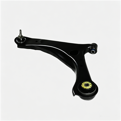
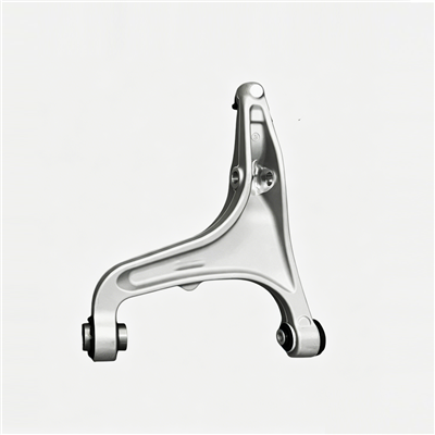
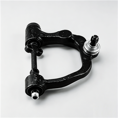
A control arm, also written as A-arm, A-frame, suspension arm, trailing arm or track control arm, is a guiding component of the suspension system. One end is connected to the subframe or the body through a bushing, and the other end is connected to the knuckle through a ball joint. It transmits longitudinal and lateral forces between the wheel and the vehicle body, controls the path of wheel motion and maintains alignment parameters such as camber and toe, and it withstands the loads generated during braking, acceleration and cornering. Bonpora builds the part as a stamped steel plate welded structure, a forged aluminium alloy part or a cast iron part, states compliance with IATF 16949, lists critical inspection as dimensional accuracy of the mounting points, welding strength, ball joint starting torque and fatigue life, and gives a warranty of two years or 50,000 km for cast and welded parts. Matching bushings and ball joints are supplied with the arm. For a fleet or a service network, the practical question is not whether an arm wears but when to look at it, and this guide sets out that schedule.
Suspension arm failures rarely arrive without warning. They build up through a bushing that softens and a ball joint that loses preload, and both are visible long before the driver reports a noise. Moving the part into the planned service is therefore a cost decision rather than a technical one.
When an arm or a ball joint fails on the road, the vehicle stops where it is, the repair happens at an unknown workshop at an unknown price, and the load arrives late. Against that, an inspection takes minutes and a planned replacement takes a bay slot. The arithmetic strongly favours inspection, and it is particularly clear for vehicles that carry a payload or a timetable.
The arm carries two wear items, the bushing and the ball joint, and both are replaceable or delivered with the arm. A maintenance plan that treats the assembly as one unit and records the condition of both interfaces allows the decision to be made on measurement rather than on the age of the vehicle, which is usually more economical over a large fleet.
The inspection interval should follow the duty, and duty is easier to describe from the route than from the odometer.
Group the fleet by the road surface, the load and the number of stop start cycles per day rather than by vehicle model alone. A delivery van on sealed city streets and the same van on rural service roads see very different loads through the same suspension arm. Two or three bands are enough to start with, and they can be refined once the workshop history has accumulated.
The band then sets the interval, because the purpose of the interval is to catch a softening bushing before the driver feels it. A fleet working on broken surfaces or carrying maximum load will move through the check earlier than a fleet on good roads, and a fleet that never leaves a sealed city route can follow the longest interval. Review the bands once a year against the actual failures and adjust the interval rather than adding parts to the schedule.
| Duty band | Typical operation | Load on the arm | Check logic |
|---|---|---|---|
| Light, sealed roads | City delivery, short trips, low payload | Low impact, many small cycles | Inspect at every scheduled service |
| Mixed | Suburban and rural routes, moderate payload | Regular bumps and cornering loads | Shorten the interval and record alignment each time |
| Severe | Unsealed surfaces, kerb contact, maximum payload or towing | High impact and high lateral load | Frequent inspection, expect earlier bushing and joint replacement |
| Special | Recovery, construction, off road service | Shock loading beyond the normal design case | Inspect after any heavy impact event, not only on the schedule |
The point of a short check is that it actually gets done, so it should need no more than the vehicle already being on a lift.
With the vehicle raised and supported, inspect the ball joint boot for splits or grease loss, look at the coating on the arm for blistering or rust staining, look at the weld areas and the rib ends for a crack, and check the bushing for cracks in the elastomer or for a bushing that has started to move in its bore. Then feel for play with a controlled pry load at the bushing end and check the ball joint by hand. Nothing on that list needs a special tool beyond a pry bar and a lamp.
Record the result as a condition, not as a yes or no. A bushing with light surface cracking and a bushing with a deep crack that opens under load are two different states, and both should be noted so that the next inspection has something to compare against. A note that says the same of both tells the next technician nothing.
| Check point | How to check | Condition that needs a decision |
|---|---|---|
| Ball joint boot | Visual, with a lamp | Split, hardened or missing boot, grease loss visible |
| Ball joint free play | Hand load with the wheel raised | Audible or visible movement, feel of a loose joint |
| Bushing elastomer | Visual plus controlled pry load | Cracks that open under load, elastomer that has taken a set |
| Bushing in the bore | Visual at the bore edge | Bushing walking out of position |
| Arm structure | Visual on the loaded face and rib ends | Any visible crack, deformation or impact mark |
| Coating | Visual on weld toes and edges | Blistering, flaking or rust staining with section loss |
| Tyre wear pattern | Visual on both shoulders | One shoulder wearing faster than the other |
Once a year, the quick check is supported by measurement, because measurement is what turns a condition into a planned replacement date.
Record camber and toe for each vehicle at the annual inspection and keep the values in the vehicle file. A single out of specification reading means the geometry needs attention now; a reading that has drifted since the previous year means a bushing or a mounting point is moving under load and should be investigated before the tyre wear appears. The trend is the useful part, not the single figure.
Where the workshop has the equipment, measure the movement at the bushing end under a defined pry load and compare it with the previous record for the same vehicle. The absolute number matters less than the change, because different arms and different bushing materials have different normal values. For the ball joint, a starting torque reading compared against the specification window is the equivalent check.
Alignment history is the cheapest predictive tool available to a fleet, because the equipment already exists at most service points.
A bushing that has softened allows the arm to move further under load, which changes the geometry as the vehicle drives. On the bench the change may be small, while under load it is larger. A camber or toe value that moves between two annual checks without an impact event points to the interface rather than to the structure, and the correct first action is an inspection of the bushing, not an adjustment of the geometry.
Keep the values per vehicle, per axle and per side, and review them at the annual fleet review. Two or three vehicles of the same model showing the same drift in the same period is a signal that the duty band for that group is too generous, which is a scheduling decision rather than a parts decision. That kind of review is what keeps a maintenance plan responsive instead of fixed.
Replacement planning should combine three inputs, and no single one of them is sufficient.
Bonpora gives two years or 50,000 km for cast and welded parts. That figure is a reference for planning, not a prediction. A vehicle on a severe duty band can reach a worn interface well inside that distance, and a vehicle on light duty can pass it with both interfaces still sound. Use the figure to decide when inspection should become frequent, and use the measured condition to decide when to replace.
Where both arms on an axle have covered the same distance under the same conditions, replacing both together keeps the axle behaviour symmetrical and avoids a second visit a few weeks later. Where only one side has impact damage, the decision on the other side can be made on its measured condition. Recording the reason for the replacement on the work order is what makes that judgement repeatable across a workshop team.
Stocking decisions should follow failure frequency, not the length of the model list.
Hold the arms that fail most often on the vehicles with the largest population, and hold the matching bushings and ball joints for the same applications. For the long tail of occasional applications, a supplier relationship with a known lead time is more economical than a shelf full of parts that turn over once every few years. The two year or 50,000 km warranty for cast and welded parts also argues for keeping the invoice and the batch reference with the stock record, so a claim can be supported without a search.
Set the quantity from the failure rate of the last twelve months plus a small buffer for a vehicle that must not be off the road. Where a vehicle class has a single high failure position, holding two of that position is usually cheaper than one delay. Review the quantities at the same time as the duty bands, because a change in route changes both.
| Position or application | Failure frequency | Stocking decision | Note |
|---|---|---|---|
| Front lower arm, high volume model | Highest | Hold arm plus matching interfaces | Most common cause of front axle noise |
| Front upper arm | Medium | Hold where the model population is large | Often replaced with the lower arm on high mileage vehicles |
| Rear trailing arm | Low to medium | Hold for the models that use it heavily loaded | Bushing condition drives the decision |
| Rare or older model | Low | Order to demand with a known lead time | Keep the supplier reference on file |
A maintenance plan improves only if the workshop writes down what it found, and the fields needed are few.
Vehicle, model, position, side, odometer, duty band, the condition of the bushing and the ball joint, the alignment values before and after, the reason for replacement, and the batch reference of the part fitted. Where a part is replaced under warranty, the installation record is also what supports the claim.
Once a year, sort the work orders by position and by duty band and look at the average distance to replacement. If a band is reaching replacement far earlier than planned, shorten its interval or re-examine the route. If a band is reaching the end of the vehicle life with the original arms still sound, its interval can be relaxed. That single review is usually enough to keep the schedule honest for the following year.
| Data field | Why it matters | Used for |
|---|---|---|
| Position and side | Identifies the pattern by application | Stocking and interval decisions |
| Odometer at replacement | Gives the distance to failure | Comparing duty bands |
| Duty band | Links the vehicle to its route | Setting inspection intervals |
| Condition recorded at inspection | Shows the progression, not just the outcome | Early replacement planning |
| Alignment values before and after | Detects interface movement | Predictive inspection |
| Part batch reference | Links the part to its production record | Warranty and quality feedback |
Some causes of arm wear sit outside the part, and they can be managed at almost no cost. Salt on winter roads attacks coating and fasteners, so washing the underside after the winter period protects both. Kerb contact during tight manoeuvres bends arms and damages ball joints, so driver briefing on approach angles pays for itself on vehicles with a low front overhang. Vehicles that operate on unsealed surfaces should have the quick check performed after any heavy impact event rather than waiting for the schedule, because an impact can start the damage that the next inspection then finds. None of these measures changes the part, and all of them change how long it lasts.
At every scheduled service for the short check, with a measured inspection once a year. Fleets on broken surfaces or carrying heavy loads should shorten the interval, and any vehicle that has taken a heavy impact should be checked immediately.
It can, but it is usually wasteful. Two or three duty bands based on road surface and load give a better result, and the bands can be adjusted once the workshop history has accumulated enough data.
Yes, because the trend matters more than the single value. A reading that has moved towards the limit since the previous service indicates an interface that is changing, which is worth investigating before the tyre wear appears.
Where both have covered the same distance under the same duty, replacing them as a pair keeps the axle symmetrical and avoids a second visit. Where one side alone has impact damage, the other can be judged on its measured condition.
Send the vehicle list, the duty bands and the current stock list to the team at Bonpora Parts and Components Co.,Ltd. for help in matching arms, bushings and ball joints to the applications that fail most often. The control arm range covers the three construction routes, the selection and specification guide explains the drawing data behind each part, the failure analysis describes the conditions to record at inspection, and the wholesale guide covers stocking decisions.