sales@bonporaparts.com
0086-10-64988621
English
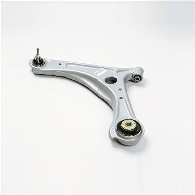
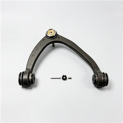
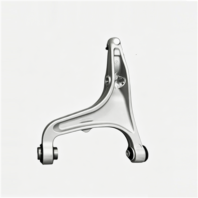
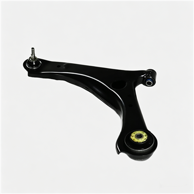
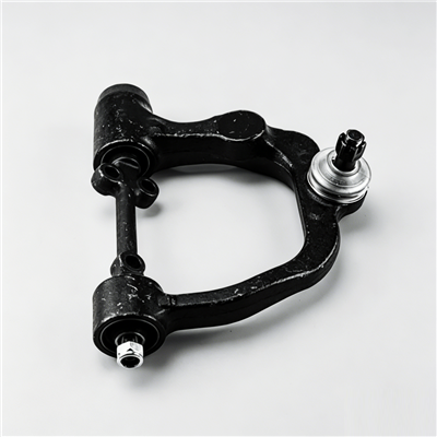
A control arm, also written as A-arm, A-frame, suspension arm, trailing arm or track control arm, guides the suspension. One end is connected to the subframe or the body through a bushing, and the other end is connected to the knuckle through a ball joint. It transmits longitudinal and lateral forces between the wheel and the vehicle body, controls the path of wheel motion and maintains alignment parameters such as camber and toe, and it withstands the loads generated during braking, acceleration and cornering. Bonpora supplies the part as a stamped steel plate welded structure, a forged aluminium alloy part or a cast iron part, states compliance with IATF 16949, and lists critical inspection as dimensional accuracy of the mounting points, welding strength, ball joint starting torque and fatigue life, with a warranty of two years or 50,000 km for cast and welded parts. Matching bushings and ball joints are supplied with the arm. This guide covers the replacement job itself: what to prepare, what to record before the first bolt moves, the removal and refit sequence, and the checks that decide whether the job is finished.
A control arm is held by a small number of fasteners, but the number is misleading, because the difficulty is in the loads those fasteners carry rather than in their count.
Typically there are three groups. The bushing end is held to the subframe or the body, either by a horizontal bolt through the bushing sleeve or by a bracket with two or three bolts. The ball joint end is held to the knuckle by a stud with a nut, by a pinched clamp, or by bolts where the joint is bolted to the arm. A third connection may exist for a stabiliser link, a height sensor or a damper. Each of those groups must be tightened with the suspension at its normal ride position, otherwise the elastomer in the bushing is pre-loaded in twist as soon as the vehicle is lowered.
Access decides how long the job takes. On many vehicles the wheel and the inner arch liner come off, and on some layouts the stabiliser link, the track rod end, the damper lower mount or an underbody shield has to be released before the arm can be swung clear. Plan the sequence on the actual vehicle rather than from a generic list, and check that the subframe does not have to be lowered before committing to the job.
Suspension work stores energy in the spring and in the arm itself, so the preparation stage is not optional.
Raise the vehicle on a level surface, support it on stands at the manufacturer points, and keep the jack in place as a secondary support. Never work under a vehicle held only by a jack. Where the arm has to be moved through its travel to reach a fastener, make sure the stand placement still allows that movement without the vehicle shifting.
The spring stores energy even with the wheel raised, and a compressed spring can release stored force when a load-carrying fastener is undone. Use a spring compressor where the procedure calls for one, keep hands and face clear of the spring axis when the last fastener is released, and never use heat on a spring or on a load-carrying suspension fastener.
Staging the tools before the vehicle goes up avoids the situation where a joint is already released and the correct tool is missing.
Sockets and spanners in the sizes for the three fastener groups, a ball joint separator or a puller, a torque wrench covering the largest fastener on the job, a pry bar, penetrating oil for a seized fastener, a wire brush, and a marker pen for recording positions. Add a torque angle gauge where the specification calls for a tightening angle rather than a value.
New nuts and bolts where the manufacturer states single use, a new ball joint boot or a complete joint where the boot is damaged, and a new bushing where only the bushing is being changed. Bonpora provides matching ball joints and bushings with the arm, which removes the risk of a fit that is close but not correct. Keep the old arm until the new one has been compared against it.
| Stage | Item | Purpose | Note |
|---|---|---|---|
| Support | Jack, axle stands, wheel chocks | Hold the vehicle safely through the whole job | Never work under a jack alone |
| Release | Sockets, spanners, pry bar | Undo the three fastener groups | Use a six point socket on a tight fastener |
| Separate | Ball joint separator or puller | Release the taper without damaging the boot | Do not hammer the joint body |
| Tighten | Torque wrench, angle gauge | Apply the specified value or angle | Use the manufacturer data for the vehicle |
| Restore | New nuts or bolts, boot, bushing | Replace single use and damaged items | Order the matching interfaces with the arm |
Two records taken before removal make the refit measurably easier, and both take only a few minutes.
Record the current camber and toe values if the equipment is available. The reading tells you whether the vehicle arrived with a geometry problem and it gives the baseline for the check after the job. A car that pulls to one side after a correctly fitted arm is usually a car that arrived with a bent mounting point or a worn opposite side arm.
Mark the position of any eccentric washer, shim pack or slotted mounting point with a pen before loosening it, and keep the shims with the bolt they came from. Photograph the assembly before disassembly if a camera is to hand, because a photograph answers more questions during refit than a memory does.
Work in a fixed order so that no fastener is released while the arm is still loaded.
One, loosen the wheel bolts with the vehicle on the ground, then raise and support the vehicle and remove the wheel. Two, release anything that blocks the arm, such as the arch liner, a stabiliser link or a height sensor bracket. Three, support the arm with a jack or a stand so it does not drop when the fasteners are released. Four, undo the ball joint nut, keeping the taper seated until the last thread. Five, release the taper with a separator or puller rather than by striking the joint. Six, undo the bushing end fasteners and lower the arm out of the vehicle. Seven, compare the removed arm with the replacement before discarding anything.
Apply penetrating oil and allow time for it to work rather than adding force and rounding the head. Where a bushing bolt has corroded into the sleeve, the bolt usually has to be cut and replaced; forcing it can tear the mounting bracket. If a fastener shears, stop and assess whether the remaining thread can be removed without damaging the bracket, because the bracket is part of the body or the subframe.
The refit is the reverse of removal, with two differences that decide whether the new arm lasts.
Fit the arm with the bushing end located in its bracket but not fully tightened, so the arm can still rotate as the other joints are lined up. Insert the ball joint stud into the knuckle and confirm that the taper is fully seated before the nut is tightened; a taper that is only partly engaged will move under load and lose torque. Where the boot must pass over a shoulder, use a suitable lubricant and check that the boot is not twisted or pinched.
This is the step that is most often skipped. With the vehicle on the ground or the suspension raised to its normal ride position, tighten the bushing end fasteners. Tightening at full droop forces the elastomer to hold a permanent twist, which shortens the life of the bushing and changes the ride height. Apply the specified values or angles in the specified order, using the vehicle manufacturer data rather than a general table.
Tightening data belongs to the vehicle and the fastener, not to a generic article, so obtain the values from the manufacturer specification for the model in front of you.
Tighten in stages where more than one fastener holds the same joint, working in a diagonal or symmetrical order. Use a calibrated wrench, and hold the wrench steady on the fastener rather than letting it lean. Replace any fastener the manufacturer marks as single use, and use the specified tightening angle after the specified value where a torque plus angle sequence is called for. Do not lubricate a thread unless the specification says so, because lubrication changes the relation between applied torque and clamp load.
Note the wrench used, the values applied, and any fastener that was replaced. Where the vehicle is part of a fleet, keeping that record with the work order supports the warranty claim, since the two year or 50,000 km coverage for cast and welded parts normally assumes matching interfaces and correct installation.
| Connection | Typical arrangement | Practice for tightening | Common error |
|---|---|---|---|
| Arm to subframe or body | Bolt through the bushing sleeve, or bracket with several bolts | Tighten with the suspension at ride position, in stages | Tightening at full droop and twisting the elastomer |
| Ball joint to knuckle | Nut on a taper stud, pinch clamp or bolted joint | Fully seat the taper, then tighten to the specified value | Hammering the joint and damaging the boot |
| Stabiliser link or height sensor | Ball stud or bracket | Refit without side load, check the link angles | Refitting under tension and shortening link life |
| Wheel bolts | Tapered bolts or nuts | Torque in a star pattern with the wheel on the ground | Leaving the final torque to a wheel gun only |
Three checks confirm that the work is complete, and they take less time than a return visit.
Measure camber and toe again and compare with the baseline recorded before removal. If the values are outside specification and no adjuster is left, look for a bent mounting point on the body or an impact-damaged opposite side arm rather than adding adjustment travel that does not exist.
Drive at low speed first, listening for a knock on small bumps and on direction changes, then at road speed to check for wander or vibration. Re-check the wheel bolt torque after a short distance, which is normal practice on any wheel removal, and inspect the new joints for boot damage or grease loss.
The faults below account for most repeat visits after a control arm job. Each is avoidable with the sequence in this guide.
Almost every one of them comes from doing a step in the wrong order: tightening before loading, separating a taper with force, reusing a single use fastener, or handing the vehicle back without an alignment check. Working strictly in order removes the temptation to save a few minutes.
| Error | Result | Correct practice |
|---|---|---|
| Tightening the bushing end at full droop | Twisted elastomer, short bushing life, ride height change | Tighten with the suspension at ride position |
| Striking the ball joint to release the taper | Damaged joint and boot, noise after the job | Use a separator or puller |
| Partially seated taper | Loose joint, loss of torque, steering play | Seat the taper fully before tightening |
| Reusing a single use nut or bolt | Clamp load below specification | Fit new fasteners where specified |
| Skipping the alignment check | Uneven tyre wear reported later | Measure camber and toe and compare with the baseline |
No. The wheel has to come off and the suspension has to be supported, so the vehicle must be raised and held on stands. The final tightening is the only step that is done with the suspension at its normal ride position.
Where the arm is supplied with matching bushings, fit them as a set. Where an existing bushing is reused, check the bore for roundness and the elastomer for cracks first, because a sound arm with a tired bushing will still produce the original complaint.
Yes. The arm sets camber and toe, so even a correctly fitted replacement changes the geometry slightly. The check also confirms that no mounting point was disturbed during the job.
Re-check the wheel bolts after a short drive, as with any wheel removal. For the suspension fasteners, follow the vehicle manufacturer service schedule, and inspect the new joints for boot condition at the same time.
Share the vehicle details, the position in the layout and the required bushing or ball joint specification with the technical team at Bonpora Parts and Components Co.,Ltd. so that the arm arrives with the correct matching interfaces. The control arm range lists the available construction routes, and the selection and specification guide explains how the drawing data is agreed, while matching mounting bushes cover the subframe end of the job.