sales@bonporaparts.com
0086-10-64988621
English
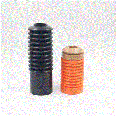
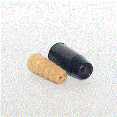
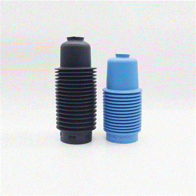
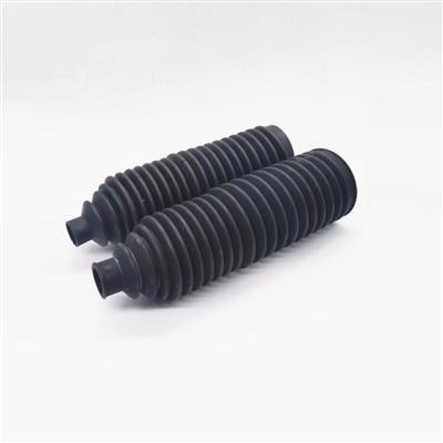
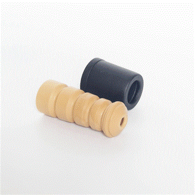
A dust cover, also called a shock dust boot, dust shield or strut bellows, is installed externally on the shock absorber piston rod, positioned above the oil seal. Its upper end mates with the piston rod and its lower end mates with the reservoir cylinder or connecting component. Compounds used in production include EPDM, nylon PA66, PU, NR, NBR and TPE, selected to suit the working temperature and the amount of flex the bellows has to survive.
Functions. It prevents external contaminants such as mud, dust and moisture from reaching the oil seal and the piston rod surface, which avoids scratching of the rod and damage to the seal. It also helps to block high temperatures and UV aging of the parts underneath it.
Service life. Design life of no less than 5 years or 80,000 km without cracking, hardening or deformation failure under conventional environmental conditions.
Quality standard. Manufactured to comply with IATF 16949 system requirements. Test items include hardness, tensile strength, ozone resistance and high and low temperature resistance from -40 C to +100 C.
Warranty. Warranty is provided with the complete shock absorber assembly. When the cover is sold separately, a 1 year or 50,000 km warranty is offered, covering material and manufacturing defects.
Customization. Moulds can be customized from customer supplied mounting dimensions, shape and colour, and different bellows profiles and material hardness adjustments are supported.
A failed dust cover is often the first visible sign that something else in the damper assembly has changed. If the replacement is fitted without understanding why the first one failed, the new cover usually follows the old one within a season. The diagnostic approach that works in a workshop is to look at three things in order: where the damage is located on the cover, what condition the damage is in, and what the rod and the seal look like underneath it. That combination separates a cover that reached the end of its normal life from a cover that was destroyed by a fitting fault, a fouling problem or a damper fault. The sections below set out the common patterns and what they point to.
| Failure Mode | Mechanism | Usual Root Cause | Action |
|---|---|---|---|
| Splits around the folds | Repeated flexing beyond the design strain | Too few ribs for the stroke, or a wall that is too thin at the fold | Review the profile against the stroke length |
| Hardening with surface cracking | Heat and ozone aging of the compound | Compound not rated for the temperature or the ozone exposure | Move to a compound with a higher temperature rating |
| Cover hanging loose on the rod | Loss of bead engagement | Bead rolled during fitting, worn groove, or a reused clip | Reseat or replace the bead and fit a new clip |
| Wear through on one side only | Mechanical rubbing | Contact with the spring, the tyre or a hose in part of the travel | Correct the routing or the profile, restore clearance |
| Ballooned and blown off the seat | Internal pressure build up | Vent hole blocked or sealed by grease or a tie band | Clear the vent and refit without excess grease |
| Grit and water found inside | Loss of the sealing overlap | Torn lower lip, missing collar, or an incorrect part fitted | Replace the cover and check the seat dimensions |
| Torn at the top during removal | Handling damage | Cover pulled off the rod before the clip or collar was released | Not a service failure, release the fastener first |
| Soft and swollen feel | Chemical attack | Contact with a solvent, a petroleum based grease or a wrong fluid | Change the assembly lubricant and the compound |
Look at the position of the split. Cracks that follow the inside of several folds point to a profile that is running out of travel, and the fix is in the drawing rather than in the compound. Cracks that radiate from a single point usually start at a small nick or at a moulding flaw, which suggests handling damage or a tooling issue on that batch.
Hardening with fine surface cracks along the outside of the bellows is the classic signature of heat and ozone aging. Check how close the cover sits to an exhaust or a brake heat source, and confirm the temperature rating of the compound against the temperature actually measured at the part. Where the cover is exposed to strong sunlight and to electrical equipment, the ozone resistance of the compound also matters.
A cover that has slipped is nearly always a retention problem rather than a material problem. Inspect the upper bead for a rolled or deformed profile, check the rod groove for wear and burrs, and confirm whether the clip is a single use item that was reused. A cover that can be rotated freely on the rod is not correctly seated.
Localised wear on a single side is a clearance fault. Move the suspension through its full travel and watch the gap between the cover and the spring, the tyre and any hose or bracket. Wear marks that appear only in the bump or only in the rebound position show where the interference occurs, and the answer is usually a routing change or a different profile rather than a different compound.
A vent is provided on many covers so that air can move as the internal volume changes. If that vent is blocked by grease, paint or a tie band fitted too high, the bellows pressurises with every stroke and finally blows off the seat or splits at the top. Probe the vent and check that no band crosses it.
Ingress points to a broken seal between the cover and the assembly rather than to the material. Check the lower lip for tears, confirm that the collar or ring is present and correctly seated, and verify that the part number fitted actually matches the seat diameter on the damper.
The two are easy to confuse, because a damaged cover and a leaking damper produce a similar complaint from the customer. The table below separates the observations.
| Observation | Points to the Cover | Points to the Damper or Seal |
|---|---|---|
| Oil film on the rod above the seal | No | Yes, the seal is passing oil |
| Grit packed inside a sound cover | Seat or lip fault | Possible if the seal has been grooving the rod |
| Scoring or pitting on the rod surface | Only if ingress was allowed for a long period | Yes, the rod is damaged and needs replacement |
| Cover split but rod and seal clean | Yes, a material or profile issue | Unlikely |
| Knocking or reduced damping with a sound cover | No | Yes, an internal damper fault |
| Cover worn on one side with a sound seal | Yes, a clearance or routing fault | No |
| Measurement | Why It Matters |
|---|---|
| Free length of the cover | Confirms whether the fitted part matches the drawing |
| Upper bead diameter | Shows whether the bead has stretched or deformed |
| Lower lip or seat diameter | Confirms the correct size was fitted |
| Number of ribs | Distinguishes similar profiles that are not interchangeable |
| Hardness feel at the fold | An approximate check for a hardened compound |
Where the cover is being returned under a warranty claim, the measurements above plus a photograph of the failure location are normally enough for the supplier to identify whether the batch, the profile or the fitting was responsible. The dimensional method used to identify a cover is set out in the dust cover material and fitment guide.
| Situation | Decision |
|---|---|
| Cover split, rod and seal in good condition | Replace the cover, check clearances before refitting |
| Cover split and rod scored | Replace the cover and the damper unit |
| Same part failing repeatedly on one vehicle model | Review the profile and the routing with the supplier |
| Same part failing early across a fleet | Review the compound and the batch records |
| Cover sound, oil film on the rod | Damper or seal work, not a cover issue |
| Cover removed for access and found sound | Refit if the bead is undamaged, with a new clip |
The first failure mode usually changes with the duty cycle, and recording it by fleet helps predict when the next replacement will be due.
| Duty Band | Most Common First Failure | Practical Response |
|---|---|---|
| Passenger car, paved roads | Age cracking after several years | Inspect at each service, replace when cracked |
| Light commercial, mixed roads | Chafing and grit ingress | Shorter inspection interval, check clearances |
| Heavy duty and off road | Tearing at the folds and seat damage | Heavier duty profile and compound |
| Racing and track use | Heat hardening near a heat source | Higher temperature compound and shielding |
Most of the failures above are removed at two stages. The first is specification: the profile has to have enough ribs and enough wall thickness for the actual stroke, and the compound has to suit the temperature, the ozone exposure and the fluids it will meet. The second is fitting: the bead must be seated without rolling, the free length must be respected, a new clip must be used, and the vent must be left open. The fitting sequence is set out step by step in the dust cover installation guide, and the controls that keep the profile and the compound consistent from batch to batch are covered in the dust cover manufacturing and quality guide. Where a fleet keeps seeing the same failure, it is worth checking the condition of the piston rods and the other shock absorber parts at the same time, because a damaged rod will shorten the life of every cover fitted over it.
A cover with cracks that reach through the wall or gaps at the seat should be replaced at the next opportunity, because grit and water are no longer excluded from the seal. A cover showing only light surface chalking and no through cracks can be monitored at the next service.
No. Hardening is a permanent change in the compound, and a treated surface does not restore the flexing properties at the folds. Replacing the part is the only reliable answer once the rubber has hardened.
The common reasons are a bead that was rolled during fitting, a cover fitted under tension instead of at its free length, the wrong compound for the temperature, a reused single use clip, or contact with another component at some point in the travel. Checking all of those points before the next fit prevents a repeat.
It helps where the failure is caused by heat, abrasion or insufficient flex life, but it will not correct a clearance problem or a fitting fault. Identify the failure mode first, then choose between a profile change, a compound change or a fitting correction.
Bonpora Parts supplies dust covers and shock dust boots in EPDM, NBR, NR, PU, TPE and nylon PA66, and our engineers can identify a replacement from the failed part itself when the original number is no longer legible. Send the free length, the bead and seat diameters, the rib count and a photograph of the failure location, and we will match the closest existing profile or review whether a different compound would suit the duty better. A trial batch with a hardness and low temperature test report keeps the first release decision straightforward. Start from the dust cover range, review the selection criteria in the dust cover selection and replacement guide, or contact our team with your failure report and annual volume. Further references are listed on the products page.