sales@bonporaparts.com
0086-10-64988621
English
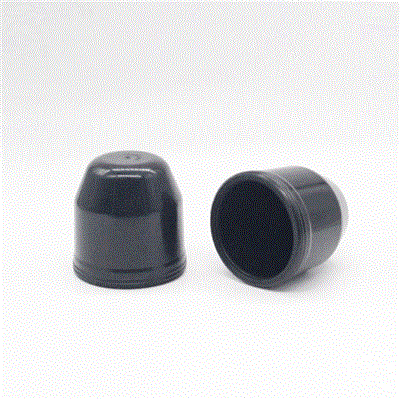
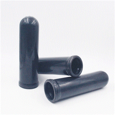
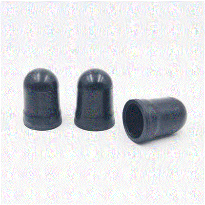
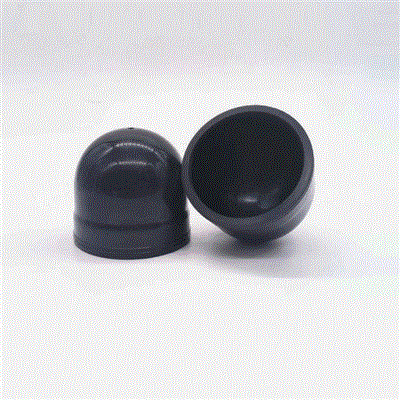
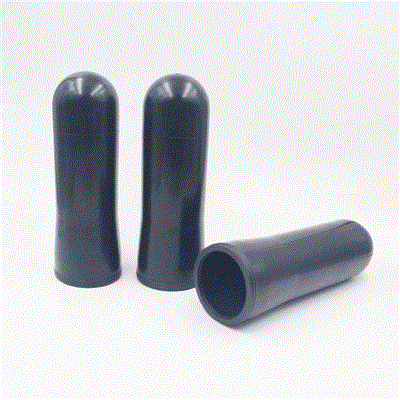
Piggyback shocks sometimes have an internal floating piston that separates oil and nitrogen. But more commonly, a rubber bladder reservoir holds the gas separately. This air bag tank is less likely to leak than a separate piston seal.
Main features:
Ensure oil and gas separation and avoid foaming
Actively prevent cavitation and improve overall impact performance
Provides consistent damping for optimal traction and control
Helps extend shock absorber life
Material: NBR, HNBR
A nitrogen gas bladder is one of the least expensive components in a piggyback shock, yet the way it is fitted and charged determines whether it survives a full service interval. Most early returns are not caused by the rubber itself. They come from a sharp edge left in the housing, a neck twisted during assembly, an over tightened clamp, or a charge procedure that trapped air on the oil side.
This procedure is written for rebuild technicians and assembly line operators who need a repeatable sequence with measurable checkpoints. It assumes the correct replacement part number has already been selected. If you are still choosing the grade and dimensions, start with our bladder selection and specification guide.
Strip the reservoir completely and clean it with a lint free cloth and a compatible solvent. Run a finger, or better a strip of thin card, around every edge the membrane will contact. Any burr that catches the card will eventually cut the bladder, so dress it with a fine stone and clean again. Do not use an abrasive that leaves grit behind.
Check the neck seat for scoring, corrosion pits, and old compound residue. A seat that cannot seal will leak no matter how carefully the bladder is fitted. Examine the cap thread, the clamp ring, and the gas valve. Replace worn caps and clamps rather than reusing them, because the cost is small compared with a comeback.
Match the part number and cure date against the job card before opening the packaging. Handle the bladder with clean, oil free hands, and keep it out of direct sunlight. If the bladder has been stored for a long time, check it for creases or a set shape before fitting.
| Item | Purpose |
|---|---|
| Regulated nitrogen source | Charging the gas side at a controlled rate |
| Calibrated pressure gauge | Verifying precharge against specification |
| Torque wrench | Cap, clamp, and valve tightening to spec |
| Assembly lubricant | Seating the neck without dry friction |
| Lint free cloth and solvent | Cleaning the bore and the seat |
| Blunt seating tool | Pushing the neck home without piercing the membrane |
| Leak detection fluid | Confirming the cap and valve are gas tight |
| Oil of the specified grade | Refilling the damper after assembly |
Use only lubricants and oils that the damper manufacturer approves. Mineral based oil is normal in this application, but the additive package matters, because an aggressive fluid will swell the bladder and shorten its life.
Apply a thin film of approved assembly lubricant to the neck and to the seat. Push the neck squarely into position by hand, then use a blunt tool to press it fully home. It should sit flat with no tilt. A neck that is partly seated will leak once pressure is applied.
As the bladder enters the housing, guide the membrane so that it folds inward in a regular pattern instead of pinching against the bore. Do not force it with a screwdriver or a sharp pick. Irregular folds become crease lines, and crease lines become cracks after a few thousand cycles.
Start the cap or clamp by hand to avoid cross threading. Bring it down evenly so the bead is compressed uniformly around the full circumference. A clamp that is tightened on one side first will deform the bead and create a local leak path.
Tighten in at least two passes, working around the cap rather than across it. Stop at the specified torque. Beyond the specification the rubber extrudes and takes a permanent set, which is a common cause of a leak that appears a few weeks after a rebuild.
Fill the oil side to the specified level and work the rod slowly through its stroke to release trapped air. Top up as the level settles. Air left in the oil side mimics a bladder fault, because the damper fades just as it would with low gas pressure, which is why the oil fill and the gas charge must be treated as one operation.
Connect the regulated nitrogen supply to the gas valve and charge slowly. A rapid fill heats the gas and gives a false reading, and it can also fold the membrane suddenly against the housing. Bring the pressure up in two stages, pause, and then take the final reading once the reservoir has equalised.
Apply leak detection fluid to the valve, the cap joint, and the neck area. Watch for a steady bubble stream rather than a single bubble from residual fluid. Record the final pressure on the job card. Then confirm the damper on a dyno where one is available, because a correct pressure reading does not prove that the valve stack or the oil level is right.
| Application | Typical precharge | Note |
|---|---|---|
| Passenger car monotube | About 10 to 20 bar | Comfort biased setup |
| Light utility and SUV | About 15 to 25 bar | Balance ride and load control |
| Off road and heavy duty | About 25 to 40 bar | Confirm with the damper developer |
Always use the figure published for the specific damper. The ranges above are orientation only, because precharge interacts with rod diameter, valve stack, and the intended load.
| Error | What happens later |
|---|---|
| Sharp burr left in the housing | Membrane cut within a few hundred cycles |
| Neck not fully seated | Gradual gas and oil leak at the cap |
| Twisted or pinched membrane | Crease cracking at the fold line |
| Cap over tightened | Bead extrusion and permanent set |
| Air trapped in the oil side | Fade that looks like low precharge |
| Charging too fast | False pressure reading and membrane stress |
| Compressed air used instead of nitrogen | Oxidation and moisture damage to rubber and oil |
Each of these errors is avoidable with a written work instruction and a short checklist at the bench. Photograph the correct seated neck position and post it at the assembly station, because a visual reference removes most of the variation between operators.
| Check | Acceptance |
|---|---|
| Gas pressure | Within the specified tolerance |
| Leak detection at valve and cap | No steady bubble stream |
| Rod movement through full stroke | Smooth, with no knock or binding |
| External cleanliness | No oil film on the gas side |
| Dyno curve | Matches the reference unit within agreed limits |
| Job card record | Part number, cure date, and final pressure logged |
Recheck the reservoir pressure at the first scheduled service and compare it with the value recorded at build. A small drop is normal, because nitrogen permeates slowly through rubber. A rapid drop points to a fitting fault, and oil on the gas side points to a membrane problem. Our bladder troubleshooting guide walks through the diagnostic steps for each case.
Keep spare bladders, caps, clamps, and piston rods on the shelf so a rebuild line never waits for parts. Consolidated ordering of shock absorber parts is described in our wholesale sourcing guide.
Only if the thread, the sealing face, and the bead contact area are in good condition. A deformed clamp will not compress the bead uniformly, and the resulting leak is often blamed on the bladder. Given the low cost of the hardware, replacing it with the bladder is the safer practice on any rebuild.
A thin film of approved assembly lubricant helps the neck seat without dry friction and reduces the chance of rolling or pinching the membrane. Use only a lubricant that is compatible with the rubber compound and the damper oil. Excess lubricant should be wiped away before the cap is fitted.
Charging compresses and warms the gas, so an immediate reading is usually high. Once the reservoir returns to ambient temperature the reading settles to the true precharge. Always record the value after equalisation, and use the same waiting period every time so that readings stay comparable.
Some loss is unavoidable because nitrogen diffuses through rubber over time. The acceptable amount depends on reservoir volume and starting pressure and should be taken from the damper manufacturer. A loss clearly faster than that figure, or any oil found on the gas side, means the bladder or its seal needs attention.
Send us the damper datasheet and the reservoir dimensions, and our engineers will confirm the correct bladder, the precharge value, and the torque figures for your assembly. We supply NBR and HNBR bladders for piggyback and remote reservoir shocks, along with related chassis and suspension components. Browse the nitrogen gas bladder category, review our product index, or contact our export team to start an enquiry.