sales@bonporaparts.com
0086-10-64988621
English
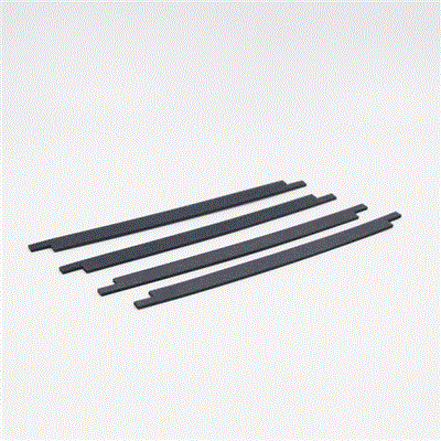
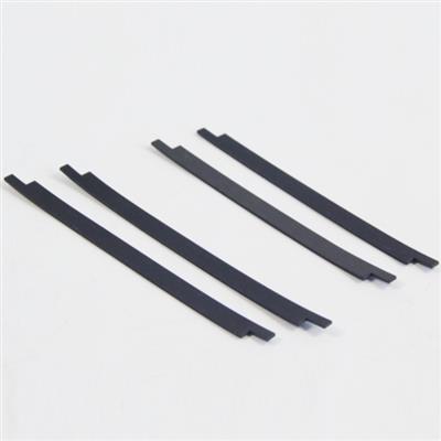
The piston ring, also named the piston band, is installed in the annular groove on the outer circumference of the shock absorber piston and reciprocates with the piston inside the shock absorber working cylinder. The main material is PTFE, polytetrafluoroethylene. Its function is to seal between the piston and the working cylinder, preventing excessive internal leakage of oil during the compression and rebound strokes so that damping force stays stable and repeatable, and in some designs to control oil flow restriction.
Fitting the band is therefore not a push on and go operation. The band has to arrive at the bore with the right interference, with its joint closed to the designed gap, and with the bore and groove in a condition that allows the two surfaces to bed in over 80,000 km or 5 years of design life. Most early band failures can be traced to something that happened during those few minutes rather than to the band itself.
Three conditions set the outcome. The groove must accept the band width without pinching and must be deep enough that the band sits proud of the piston land by the intended amount. The bore must be round and free of scoring, because a band cannot seal against a surface that is out of shape. The joint, whether it is a Z cut or a V cut, must be positioned and closed as designed, because an open or misaligned joint is a direct leak path.
Rubber seals deform and spring back; PTFE bands are stiffer and take a set. A band that is stretched over a sharp edge, folded, or twisted on fitting will not recover its shape, and the distorted section will not contact the bore evenly. PTFE is also sensitive to scratching, so a bench habits matter: a burr on a ring compressor can cost a band before the unit is closed.
Measurement before opening anything is what stops a repeat failure. If the bore is already out of round, the correct decision is to replace the assembly rather than to fit a band.
| Measurement | Record | Reason |
|---|---|---|
| Bore diameter | Two axes at top, middle and bottom | Proves roundness and taper |
| Bore surface | Photograph of any scoring | Shows whether sealing is possible |
| Groove width | Across the groove at three points | Selects the correct band width |
| Groove depth and land | Depth from the land surface | Sets how far the band stands proud |
| Rod and piston straightness | Dial gauge reading | Misalignment loads the band unevenly |
| Old band condition | Photograph of the joint and the wear face | Explains why the previous band failed |
An excessively tight groove pinches the band so that it cannot expand, and the joint then opens wider with temperature. An excessively wide groove allows the band to rock, which produces uneven bore contact and localised wear. Both conditions are measurable and both should be recorded before the new band is selected.
Check for scores along the stroke path, for a polished band where the old ring ran, and for corrosion near the ends of travel. A polished band is normal. A scored or corroded bore will abrade the new band, and no change of material will compensate for it.
A piston that does not run true presses the band against one side of the bore on every stroke. The result is a band that wears a flat on one side and leaks on the other. Check the rod for straightness and the guide bush for wear before assembly is started.
| Item | Purpose |
|---|---|
| Bore gauge and internal micrometer | Bore diameter and roundness |
| Calliper and depth gauge | Groove width and depth, band dimensions |
| Feeler gauges or strip gauges | Installed gap measurement |
| Dial gauge and surface plate | Rod and piston straightness |
| Lint free cloths and cleaning solvent | Groove and bore preparation |
| Ring compressor or fitting sleeve | Bore entry without damaging the band |
| Intended damper oil | Lubrication compatible with the system |
| Inspection light and camera | Evidence for the job record |
The cut in the band is what allows it to be fitted and to expand against the bore. The installed gap is the size of that cut when the band sits in its groove at the temperature it will see in service.
PTFE expands as it warms, so a gap that looks correct on a cold bench closes when the damper is worked hard. A gap set too small will close completely, and the two faces of the joint then press against each other, which scuffs the band and can distort it off the bore. A gap set too wide leaves a continuous leak path and reduces damping force. The correct setting is the one that stays open at the lowest service temperature and still supported at the highest, which is why the gap is measured on the actual piston rather than taken from a nominal table alone.
Fit the band into the groove without compressing it into the bore, check that the width sits squarely, and measure the joint opening. Compare the result with the joint opening measured with the band compressed to bore diameter, using the fitting sleeve if necessary. The two readings together describe what will happen once the piston enters the cylinder.
| Check | Method | Target condition |
|---|---|---|
| Free gap in groove | Feeler gauge at the joint | Open enough to allow expansion |
| Compressed gap | Measure inside the fitting sleeve | Still open at bore diameter |
| Joint alignment | Visual, then feeler check | Faces flush, no step on the sealing face |
| Band proud of land | Straight edge across the piston land | Even, small uniform stand out |
Clean the groove with solvent and a lint free cloth until no residue remains, then dry it with clean air. Work round the groove with a brass scraper or a soft tool to remove any built up deposit from the previous band, and check the groove edges for burrs. Never use a file or emery paper on the piston land.
Warm the band slightly if the compound is stiff, then fit it by hand, feeding one end into the groove and working round without stretching. Do not use pliers, screwdrivers or any tool that can nick the sealing face. Keep the joint away from ports and edges while the band is being seated.
Bring the joint together in the design direction, with the stepped overlap of a Z cut interleaved or the angled faces of a V cut in contact as intended. Check that the two ends are level with the rest of the band and that nothing has been trapped between the faces.
Lubricate the band and the bore with the intended damper oil, then use a fitting sleeve or ring compressor with a generous lead in and no sharp internal edges. Enter the bore squarely. If the piston stops, withdraw it, check the joint, and try again rather than forcing it, because forcing distorts the band and can shear the joint.
After assembly, work the unit slowly through its full stroke several times to distribute oil and displace trapped air, then check the behaviour before the unit is closed up and painted.
| Check | What to look for |
|---|---|
| Stroke feel | Even resistance in both directions, no sudden free movement |
| Noise | No scraping or clicking at low speed |
| Force trace | Close to the reference curve after bleeding |
| Oil at the rod | Clean rod, no film building up after cycles |
| Joint position | Joint remains closed and correctly aligned |
| Defect found after assembly | Fitting cause | Prevention |
|---|---|---|
| Band cut or nicked | Sharp edge on the sleeve or groove | Deburr tools, inspect the sleeve |
| Joint open or stepped | Incorrect closure direction | Follow the Z or V design direction |
| Band twisted in the groove | Forced entry into the bore | Withdraw and refit instead of forcing |
| Flat spot after short service | Bent rod or worn guide bush | Measure straightness before assembly |
| Band too proud of the land | Wrong band thickness | Select by groove depth measurement |
| Early leakage | Gap too wide or bore scored | Set the gap on the piston, check the bore |
A band that has already run in a cylinder should not be refitted to a different bore. It has taken the shape of the surface it ran against, and moving it to another unit leaves areas of poor contact. Where the same unit is being reassembled after a seal change, inspect the joint, the sealing face and the groove, and refit the band only if it is undamaged and its dimensions are still within the released tolerance. Where the piston itself is being replaced, match the new band to the piston groove dimensions using the Bonpora customisation route, which accepts drawings or samples with matching design according to piston dimensions and supports different diameters, thicknesses, gap configurations and materials.
Both. Measure the free gap with the band sitting in its groove, then measure again with the band compressed to bore diameter in a sleeve. The first figure shows the room available for expansion, and the second shows whether the joint is still open in the working condition. Recording the pair on the job sheet makes a later complaint easy to assess.
Only if the band is undamaged, dimensionally within tolerance and returned to the same bore it was run in. A band takes a set against the surface it has run against, so a band moved to a different cylinder will not seal evenly. For a warranty repair a new band is the safer choice.
The common causes are a joint that was closed in the wrong direction, a band nicked during bore entry, a band of the wrong thickness standing too proud or sitting too deep, and a bore that was already scored or out of round. Each is detectable with the measurements listed for pre work inspection, which is why they are worth taking before the unit is assembled.
Enough to wet the band and the bore so that the piston enters without dragging, using the oil the damper is filled with rather than a general purpose grease. Excess oil is not a substitute for correct dimensions, and a grease that is not compatible with the system can change the damping behaviour or attack the compound.
Bonpora supplies PTFE piston rings, also named piston bands, for the annular groove on the shock absorber piston, sealing between the piston and the working cylinder to keep damping force stable and repeatable, with a design life of no less than 80,000 km or 5 years, a 1 year or 20,000 km warranty, and customisation of diameters, thicknesses, gap configurations and materials against customer drawings or samples. Start from the piston ring range, review the technical background in the piston ring and piston band guide, understand the wear patterns in the piston ring failure analysis guide, check the mating parts in piston rods and shock absorber parts, and send your piston data through the contact page.