sales@bonporaparts.com
0086-10-64988621
English
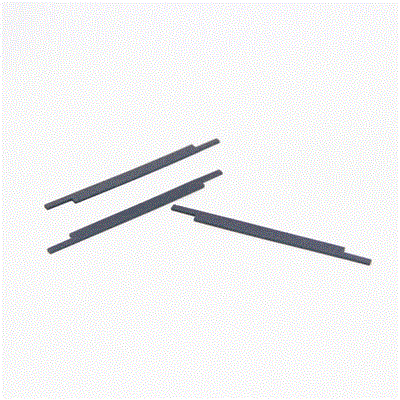
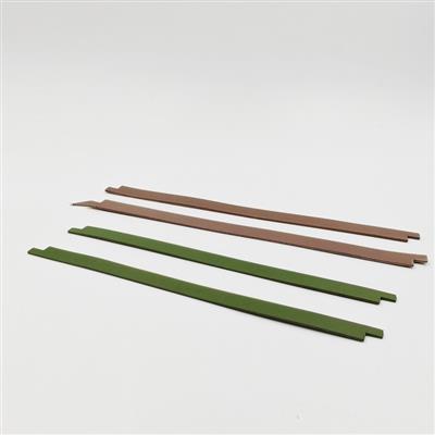
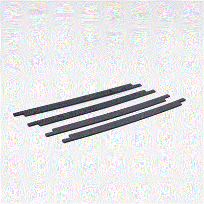
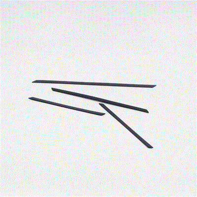
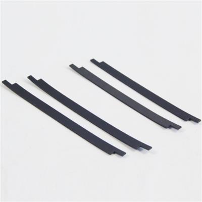
A piston ring, also called a piston band, is the thin PTFE sealing element that sits in the annular groove machined into the outer circumference of a shock absorber piston. It reciprocates with the piston inside the working cylinder and provides the seal that keeps oil from leaking past the piston during compression and rebound strokes. That seal is what makes the damping force stable and repeatable. When the ring is the right size for its groove, the design life of no less than 80,000 km or 5 years is realistic and the shock absorber keeps its basic performance even after normal wear. When the ring is sized wrong, internal leakage rises and the driver feels it as a vague, inconsistent, or noisy damper long before any external part looks worn.
This guide covers the measurements, cut geometries, and clearance rules that engineers, rebuild shops, and purchasing teams need in order to specify a PTFE piston ring that fits the first time. It complements our general piston ring selection overview with the numerical detail that goes onto a drawing or a purchase order.
The piston ring separates the two oil volumes inside the working cylinder. Every stroke pushes oil through the piston valving, and the ring limits how much oil bypasses that valving around the outside of the piston. Bypass flow is a function of the contact pressure between ring and bore, which in turn is a function of free length, cut geometry, ring thickness, and groove depth. A ring that is slightly too short will not close the gap at operating temperature and will bleed oil continuously. A ring that is too long will buckle outward, raise sliding friction, and create a stick slip feel at low shaft speeds.
Because the effect is hydraulic rather than mechanical, sizing errors rarely cause a visible failure. They show up as spread between the compression and rebound curves measured on a dynamometer, as a force loss after the damper warms up, or as a difference in behaviour between left and right sides of the same axle. For a fleet engineer, that means the ring is a calibration part, not a consumable gasket.
The groove is a rectangular channel turned into the piston body, and the ring is a split band of PTFE that snaps into it. The groove floor diameter sets the inner support, the groove width controls side clearance, and the groove depth plus ring thickness sets how far the ring stands proud of the piston skirt. The band must stand slightly proud in order to be pressed against the cylinder wall, but no more than the elastic range of PTFE allows. Excessive protrusion causes edge loading and rapid wear on the band corners, while insufficient protrusion leaves the band floating and leaking.
The diagonal Z cut or the V cut is what allows the band to be opened, slipped over the piston, and closed again. The cut removes a small amount of material, so the installed circumference is always slightly smaller than the nominal band circumference. The cut angle and the cut width therefore change the effective installed length and must be declared on the drawing. Two rings with identical nominal length but different cut widths will not produce the same installed seal.
Measure the bore at three heights and in two perpendicular directions, using a bore gauge with a resolution of 0.01 mm. Record the maximum, because the ring has to seal against the largest diameter it will ever see, including the slightly larger zone near the cylinder ends where wear is lowest.
Use a depth micrometer for groove depth and a set of flat blade gauges or a groove width gauge for the channel width. Groove width matters because PTFE expands more than steel when hot, and a band with too little side room will bind in the groove and stop sealing.
Free length is the length of the band as delivered, measured along the outside of the curved strip. Installed length is free length minus the cut allowance, and it is the number that must match the piston circumference at the groove floor. Always state which of the two values you are quoting when you send an enquiry.
Our standard callout is Length x Width x Thickness in millimetres, with the cut type stated separately. The table below lists the sizes held in the standard tooling range, all available with either Z cut or V cut. Custom diameters, thicknesses, gap configurations, and materials are produced from customer drawings or samples.
| Length (mm) | Width (mm) | Thickness (mm) | Cut options | Typical use |
|---|---|---|---|---|
| 178 | 5 | 1.0 | Z / V | Large bore monotube dampers |
| 163.5 | 7 | 1.0 | Z / V | Heavy duty twin tube pistons |
| 162 | 10 | 1.5 | Z / V | Wide piston band, high side load |
| 162 | 8 | 1.5 | Z / V | General automotive rear dampers |
| 149 | 8 | 1.5 | Z / V | General automotive front struts |
| 149 | 4 | 1.5 | Z / V | Narrow groove, low friction builds |
| 149 | 10 | 1.5 | Z / V | High damping force pistons |
| 137 | 4 | 1.5 | Z / V | Compact passenger car dampers |
| 130.5 | 8 | 1.5 | Z / V | Light vehicle and motorcycle units |
Both profiles are diagonal splits. The Z cut has square shoulders and a stepped overlap, which gives a positive interlock against axial movement and resists rolling of the band inside the groove. The V cut has angled faces and closes more evenly, which makes it easier to install without stressing the band ends and slightly reduces local pressure peaks at the joint. Neither is universally better; the choice follows the groove design and the assembly method already in use.
| Feature | Z cut | V cut |
|---|---|---|
| Interlock against axial shift | High, stepped shoulder | Moderate, angled faces |
| Installation effort | Higher, needs care to seat ends | Lower, closes progressively |
| Pressure peak at joint | Concentrated at shoulder | Spread over the angled face |
| Best suited to | High force, wide band pistons | Thin bands, automated assembly |
| Effect of cut width | Directly reduces installed length | Directly reduces installed length |
The end gap is the visible opening between the two cut faces once the ring is installed in the groove. A small positive gap is required so that thermal expansion can close it without creating metal to metal hoop stress. A gap that is too large becomes a permanent leak path; a gap that is closed at room temperature will open into a buckle at operating temperature.
Radial squeeze is the interference between the ring outer surface and the bore. Side clearance is the difference between groove width and ring width. Both are normally specified as ranges rather than single values, and both must be checked on the assembled piston rather than on the loose ring.
| Parameter | Typical target | If too small | If too large |
|---|---|---|---|
| End gap (cold) | Small positive gap, set by groove length | Buckle risk at high temperature | Continuous internal leak |
| Radial protrusion | Enough to preload the band, within elastic range | Floating band, weak seal | Edge loading, fast wear |
| Side clearance | Fits groove width with thermal room | Binding, sealing face lifts | Chatter and oil pumping |
| Band thickness | Matches groove depth to give flat seating | Rocking in groove | Cocked band, poor contact |
PTFE has a thermal expansion rate several times that of steel. Over the normal damper operating range the band grows more than the piston body and more than the cylinder wall, so a clearance that looks generous on a cold bench can close up in service. The end gap must be calculated at the highest temperature the damper will see, not at room temperature. For units that run hot, a slightly larger cold gap is the safer choice.
Sealing elements also pick up a small amount of oil and moisture over time, which adds a further, slow dimensional change. Well stabilised PTFE compounds limit this effect, but the effect is never zero, so the design should leave a margin rather than relying on an exact zero gap fit.
Not every piston uses a straight sided groove. Some designs use a shallow channel that relies on the band being slightly preformed, others use a deeper pocket with a retaining shoulder. Before quoting a ring, confirm which groove type the piston uses and whether the band is expected to be flat, pre-curved, or step formed. A flat band in a preformed groove will not seal at the centre of the contact patch, and a preformed band in a flat groove will sit high on its edges. Customisation based on customer drawings or samples is the normal route for these cases, and a matching design review against the piston dimensions is part of the quotation.
Most field complaints that are blamed on ring material are actually fit problems. The table below links the symptom reported by the workshop to the measurement that is normally out of specification.
| Symptom | Likely sizing cause | Check |
|---|---|---|
| Damping fades after warm up | End gap too large, or gap set at room temperature only | Cold gap value versus hot gap calculation |
| Stiff, notchy low speed feel | Radial protrusion too high | Ring thickness versus groove depth |
| Oil weeping into the gas chamber | Installed length short, cut width not accounted for | Free length minus cut allowance |
| Band cracked at the joint | Cut faces butted closed during installation | Cut geometry and assembly method |
| Chatter under small inputs | Side clearance excessive | Groove width versus ring width |
| Uneven wear around the band | Bore scored, or band not concentric in groove | Bore roundness and groove concentricity |
A complete enquiry should carry the piston reference, the groove dimensions, the required installed length, the cut type, the compound, and the annual quantity. When the application is new, a small sample order is the fastest way to verify fit, because dimensional agreement on paper does not guarantee the same contact pattern in the real groove. The first article check should record the end gap in the assembled state, the radial protrusion measured with a dial indicator, the side clearance with a flat gauge, and a visual check of the contact face after a short run in period. Keeping those four numbers in the drawing file removes most of the back and forth on repeat orders.
Our rings are produced under IATF 16949 quality management. The piston ring manufacturing guide explains how pressed and sintered PTFE stock is machined and inspected, and the installation guide covers assembly sequence, seating temperature, and the checks performed after the piston is back in the cylinder.
The installed length along the groove floor, because everything else follows from it. State whether the figure you supply is free length or installed length, and include the cut type and cut width so the factory can convert between the two correctly.
Only after checking the groove. The cut profile changes how the band closes and where the pressure peak sits, so a substitution should be confirmed against the piston drawing or by sampling. If the groove was designed around a V cut, staying with a V cut is the low risk choice.
No. A small positive gap is needed to leave room for thermal expansion of PTFE and for the slow dimensional change that follows fluid absorption. A cold gap that is already closed will become an outward buckle once the damper reaches operating temperature.
The published design life is no less than 80,000 km or 5 years, and the ring is expected to keep an effective seal even after normal wear. A 1 year or 20,000 km warranty is offered on the element itself. Actual service life depends on bore condition, oil cleanliness, and operating temperature.
Send the piston drawing, the groove dimensions, and the cut preference, and our engineering team will confirm the matching ring geometry, the compound, and the sample plan. Different diameters, thicknesses, gap configurations, and materials are all produced to customer drawings or samples. Review the piston ring range, browse the wider shock absorber parts catalogue, or contact our sales engineers with your sizing data and annual volume.