sales@bonporaparts.com
0086-10-64988621
English
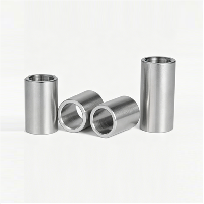
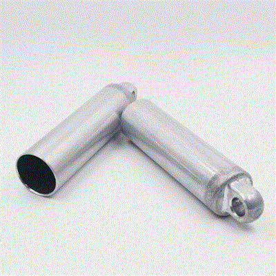
A sleeve, also called a bushing or a tube, is installed inside a hole or on the exterior of a shaft type part. It appears in connection structures, in pipe and wire passageways through walls, and at the bushing positions of moving components. Its duties are to protect wires, pipes and moving parts from abrasion, to act as a spacer that positions adjacent components and controls axial or radial clearance, and to withstand radial pressure or provide a low friction surface.
When one of those duties stops being met, the sleeve is a useful witness. Its wear pattern shows where the load was applied, its bore shape shows whether alignment was correct, its outside diameter shows whether the press fit held, and its surface shows what the environment has been doing. This guide covers the failure modes worth looking for, how to confirm each one on the bench, and the point at which a sleeve should be replaced rather than simply refitted.
The classic bushing failure. Wear is concentrated on the loaded flank, so the bore becomes oval rather than uniformly larger. The cause is usually a load that always arrives from the same direction, combined with no effective way for lubricant to reach that side. A sleeve that is greased from a single point, or that has no lubrication route at all, will wear this way even when the clearance was correct at assembly.
Where the movement between the sleeve and its counterface is very small, the surfaces do not slide cleanly; they fret, producing fine oxide debris and a dull, pitted track. Stainless against stainless is the worst combination, and aluminium against aluminium is similar. Galling, where material is torn from one surface and welded to the other, is the more severe form of the same problem and usually ends with the parts seized together.
A sleeve that was pressed into a housing can lose its grip. The usual reasons are insufficient interference at manufacture, a housing material that yields under the pressing load, thermal cycling that opens the bore of the housing, or vibration that works the sleeve outward. The visible sign is a polished ring around the outside diameter where the sleeve has been moving, or a worn shoulder where it has been hammered against a stop.
A thin walled sleeve driven into a hole with a hammer rather than a press collapses or bell mouths at the leading edge. The bore closes, the running clearance disappears and the assembly may seize on first movement. The damage is done before the part ever sees a load, which is why installation method belongs in the process specification.
Sleeves sit in the narrowest gap in an assembly, where moisture collects and stays. Steel sleeves corrode from the ends and from the bore. In a mixed metal assembly the risk is higher: an aluminium sleeve in a steel housing, or a stainless sleeve in an aluminium housing, forms a galvanic pair, and the less noble metal is consumed. The practical result is often a sleeve that cannot be removed without destroying the housing bore.
Where a sleeve lines a passageway, the failure is measured in wall thickness rather than in clearance. A cable or hose that rubs against the same point of the bore for thousands of cycles will cut a groove through the wall, and once the wall is breached the sharp edge of the panel becomes the wear surface. The bore finish and the generous lead in radius are the two features that delay this.
| Symptom | Evidence on the removed sleeve | Most likely cause |
|---|---|---|
| Play or knock at a pivot | Oval bore, polished on one flank | Wear from a single direction load, poor lubrication |
| Parts seized together after service | Pitted track, torn metal, bright weld spots | Fretting or galling, often stainless on stainless |
| Sleeve has moved in its housing | Polished band on the outside diameter, worn shoulder | Loss of press fit, housing yield, thermal cycling |
| Assembly will not turn after build | Bell mouthed bore, closed down end | Crushed during installation, wrong pressing method |
| Cannot remove the sleeve | Corrosion product between sleeve and housing | Galvanic pair plus trapped moisture |
| Wire or hose damaged inside a passage | Groove or breakthrough in the bore wall | Abrasion, sharp bore edge, undersized wall |
| Excess noise or vibration at a bushing | Uniform but excessive bore clearance | Running clearance too wide for the duty |
Take readings at two positions along the length and in two directions at each position, and compare the maximum and minimum. An oval bore points to a directional load, a tapered bore to misalignment, and a uniformly enlarged bore to simple wear or to an initial clearance that was too wide.
Compare the outside diameter along the length of the sleeve. The end that was pressed in first usually keeps its original size if the press fit held; a reduction towards one end suggests the sleeve was distorted or was machined with a taper. A band of polished metal across the full circumference means the sleeve has been rotating in the housing.
A smooth, polished flank is normal wear. A dull grey pitted track is fretting. Torn metal, weld like deposits or a roughness that catches a fingernail is galling, and it usually means the counterface is also damaged.
The shaft or pin that ran inside the sleeve is evidence too. A worn shaft will destroy a new sleeve quickly, so measure it before deciding that replacing the sleeve alone will solve the problem. The same applies to the housing bore: if it has opened up, a standard interference will not hold the replacement sleeve.
Misalignment is a common hidden cause of one sided wear. If the two bushing positions in a joint are not coaxial, or if the bracket deflects under load, the sleeve will be loaded on one flank regardless of how well it was made. In that case the drawing, not the sleeve, is the item to change.
The table below lists the measurements worth recording when a sleeve is removed, together with the interpretation that usually follows. Absolute limits belong on the drawing of the specific part; the purpose here is to make the comparison against a new sleeve meaningful.
| Measurement | Compare against | Interpretation |
|---|---|---|
| Bore, two directions at both ends | Bore of a new sleeve and the drawing tolerance | Ovality means directional load; taper means misalignment |
| Outside diameter along the length | Original outside diameter and interference value | Reduction means the press fit has been lost or the part distorted |
| Wall thickness at four points | Drawing wall thickness | Eccentric bore or local collapse |
| Length | Drawing length | Shortening means the ends have been hammered against a stop |
| End face squareness | Square to the axis | Poor squareness changes the assembled gap in spacing duty |
| Surface condition of bore | New sleeve finish | Fretting, galling, corrosion product, abrasion groove |
| Shaft or pin diameter | Nominal with tolerance | A worn counterface will damage a replacement sleeve |
Not every failure is cured by fitting a new sleeve. Where the cause lies in the housing, the counterface or the joint design, a replacement will follow the original into the same failure, so the decision table below is worth working through before the parts are ordered.
| Finding | Default action | When a change is justified |
|---|---|---|
| One sided bore wear, counterface good | Replace the sleeve, improve the lubrication route | If wear repeats, review the clearance range and the bore finish |
| Fretting or galling | Replace both parts, introduce a different material pair | Where stainless on stainless is unavoidable, specify a dry film lubricant or a bronze sleeve |
| Press fit lost, housing bore still in tolerance | Refit with the specified interference and a pressing tool | If the housing is soft, add a shoulder or a retaining compound |
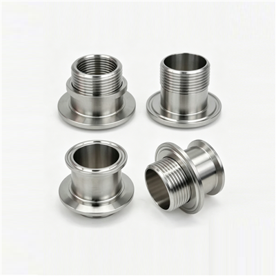
| Housing bore opened up | Replace or reclaim the housing | A larger outside diameter sleeve, or a flanged sleeve, may be the practical answer |
| Sleeve crushed at installation | Replace and change the fitting method to a press or a draw bolt | Where access prevents a press, increase the wall thickness |
| Corrosion or galvanic attack | Replace with the specified coated or stainless type | Where the joint is exposed year round, add a barrier coating or change the material pair |
| Abrasion breakthrough in a passage | Replace, dress the panel edge and the bore lead in | Where the duty is severe, increase the wall and specify a smoother bore |
Three changes remove most repeat sleeve failures. The first is material pairing, because choosing a bronze or copper alloy sleeve against a steel shaft, or a coated steel sleeve in an aluminium housing, removes the galvanic and galling routes at the specification stage. The second is the lubrication and clearance window, because a bushing that is given a defined clearance range and a route for lubricant to reach the loaded side will wear evenly instead of on one flank. The third is the installation method, because a sleeve that is pressed with a properly sized driver rather than driven with a hammer keeps its bore round. Where a sleeve also carries a protective duty, the wall thickness and the lead in radius should be reviewed at the same time, since a passage sleeve that wears through is a design limit rather than a manufacturing defect. Finally, a reference sample kept from the approved first article makes later wear comparisons meaningful: measuring a worn part against a remembered dimension is far less useful than measuring it against the part that was signed off.
Sleeves rarely fail alone. At a pivot they work with the rubber or polyurethane element around them, and a worn sleeve usually means the mounting bush in the same stack is due for replacement as well. Where a sleeve also sets the position of a component, the trouble is often reported as a gap or alignment fault rather than as a sleeve fault, and the same reasoning applies to spacers and shims elsewhere in the assembly. For a wider view of machined parts that are specified the same way, see the metal components range, and for the choice between materials and duty types, the sleeve selection guide covers that ground in detail.
Not automatically. A harder sleeve wears more slowly but transfers wear to the shaft, and a worn shaft is usually more expensive to replace than a sleeve. The better approach is to keep the sleeve as the sacrificial part, choose a material pair that avoids galling, and confirm that the clearance and lubrication suit the duty.
Either the interference at manufacture was too small, the housing material yielded during pressing or in service, or the assembly vibrated enough for the sleeve to work outward. Check the housing bore against the drawing first, because if it has opened up, a standard replacement sleeve will come loose in the same way.
Often, but it depends on how much corrosion product has formed. A penetrating lubricant, applied for several hours, followed by a draw bolt or a press is the least damaging route. Where galvanic corrosion has welded the sleeve into an aluminium housing, cutting the sleeve in one place and collapsing it inward is usually safer than pulling it out with force.
The drawing of the specific part carries the limit, and it is normally expressed as a maximum clearance rather than as a wear figure, because the shaft diameter has to be taken into account. Measure both the bore and the shaft, add the two deviations, and compare the total against the specified maximum clearance for the joint.
Send Bonpora Parts and Components Co.,Ltd. the failed sleeve, the joint drawing, the measured shaft and housing dimensions and a note of the service conditions, and the engineering team will comment on the failure mechanism and propose a material, clearance or wall thickness change where one is justified. Sleeves are supplied in low carbon steel, stainless steel, copper alloy and aluminium alloy, with customisation of lengths, inner and outer diameters and chamfer forms from a drawing or a sample. See the sleeve, bushing and tube range or contact the team directly.