sales@bonporaparts.com
0086-10-64988621
English
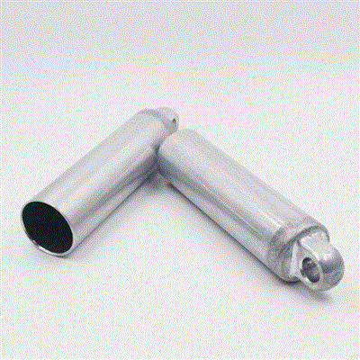
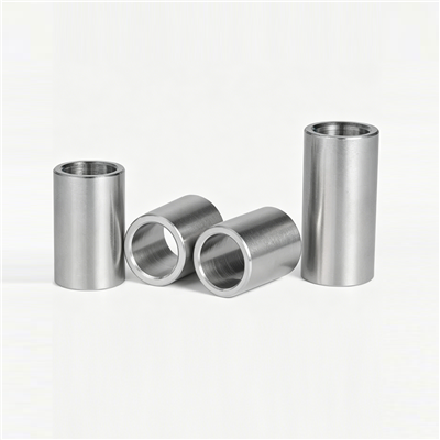
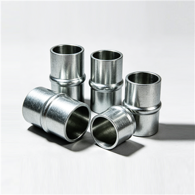
A sleeve, also supplied as a bushing or a tube, is installed inside a hole or on the exterior of a shaft type part. It is found in connection structures, in pipe and wire passageways through walls, and at the bushing positions of moving components, where it protects wires, pipes and moving parts from abrasion, spaces adjacent components to control axial or radial clearance, and withstands radial pressure or provides a low friction surface.
A sleeve can be made perfectly and still fail on the first day in service if it is fitted badly. Pressing it in crooked, driving it with a hammer, or leaving a burr on the housing edge will close the bore or tilt the part, and the assembly will either seize or wear on one flank from the start. The procedure below is written for the workshop and for the process engineer who has to write the work instruction, and it covers the three common situations: a sleeve pressed into a housing, a sleeve fitted onto a shaft, and a sleeve lining a passageway through a panel.
Every fitting problem that can be detected before a sleeve is touched should be detected before the sleeve is touched, because at that point the part is still reusable.
Take readings in two directions at both ends of the bore and record the maximum and minimum. Compare them with the drawing and with the outside diameter of the sleeve to confirm the intended interference. An oval or tapered housing bore will produce an oval sleeve however carefully it is pressed, and a housing bore that has already opened up will not hold a standard replacement at all.
Look for a chamfer or radius at the mouth of the bore and remove any burr left by the previous sleeve or by a machining operation. A raised edge will shave metal from the outside diameter of the sleeve as it enters and will also tilt it. On an aluminium housing, a light deburr with a scraper is safer than a file, which can remove more material than intended.
Wipe the bore and the sleeve free of chips, cutting fluid, grease and corrosion product. A dry, clean interface is what makes the interference predictable. Where a retaining compound is specified, the manufacturer will state the required surface condition and the cure time; follow that rather than applying the compound to an oily surface.
Measure the shaft, pin or bundle that will run in or pass through the sleeve. A worn shaft will destroy a new sleeve quickly, and an oversized bundle will not pass through at all. This is the step most often skipped in a hurried repair.
| Method | Best suited to | What to watch |
|---|---|---|
| Arbor press or hydraulic press | Standard workshop fitting, most interference fits | Keep the sleeve square to the bore; use a pilot or a stepped driver |
| Draw bolt or threaded puller | Blind bores, awkward access, thin walled sleeves | Pull rather than hammer; lubricate the thread and the nut face |
| Soft faced mallet with a driver | Small sleeves, minimal interference, light duty | Easy to tilt and to bell mouth the leading edge; use only where the wall is thick |
| Thermal shrink of the housing or cooling of the sleeve | Heavy interference, large diameter, delicate housings | Respect the temperature limits of the material and of any coating |
| Retaining compound with a slip fit | Housings that cannot take a press fit, or field repair | Cure time and cleanliness; the joint holds by adhesion, not by interference |
Set the housing so that the bore is fully supported and square to the press ram. A housing supported on one side will flex as the sleeve enters, which opens the bore and reduces the interference on the loaded side.
Use a pilot, a stepped driver or a draw bolt that engages the sleeve bore. Contact the sleeve on its end face only, never on a chamfer or on the bore edge, and check that the sleeve is square with a rule in two directions before applying force.
Apply force progressively and keep the sleeve moving. Stopping part way and restarting is what causes the sleeve to cock in the bore. If the force rises sharply, stop and investigate rather than pushing harder, because a sudden increase usually means the sleeve is not square or that a burr has been picked up.
Press until the sleeve is fully seated against its shoulder or to the specified depth, then check the position with a depth gauge or a straight edge. A sleeve left proud of the face changes both the clearance and the appearance of the joint.
Measure the bore again. Pressing reduces the bore slightly by elastic recovery of the housing, and a sleeve that measured inside tolerance before fitting may not do so afterwards. Ream or hone only where the drawing allows it.
Where the sleeve fits over a shaft rather than inside a housing, the interference is on the inside diameter and the sleeve is usually heated rather than pressed. The shaft should be clean and free of burrs, and the sleeve should be heated uniformly, in an oven or an oil bath where the material allows, rather than with a local flame that will distort one side. Slide the sleeve on in one movement and hold it against its shoulder until it grips, then allow it to cool naturally. If the sleeve is a protection sleeve rather than an interference fit, the objective changes: it should be a light push fit so that it can be replaced in the field without heat, and it should be retained by a shoulder, a snap ring or the clamping action of the surrounding joint.
A passageway sleeve has to protect its contents from a panel edge, so the position matters as much as the fit. Allow the sleeve to protrude slightly on both sides of the panel rather than finishing flush, so that a cable or hose cannot come into contact with the metal edge during assembly or in service. Use a flanged sleeve where the panel is thin, since the flange spreads load and stops the sleeve from being pushed through. Push the sleeve in by hand or with a soft faced mallet; a passage sleeve usually needs retention rather than interference, and forcing it will crack a plastic panel or deform a thin metal one.
The table below gives the intention of each interface rather than a substitute for the drawing, since the correct figure depends on housing material, wall thickness and duty.
| Interface | Fit intention | Installation note |
|---|---|---|
| Sleeve outside diameter into a steel housing | Light interference, pressed | Pilot the sleeve and use a press or draw bolt |
| Sleeve outside diameter into an aluminium, plastic or cast housing | Lighter interference, or a flange and a retaining compound | Avoid heavy pressing that could yield the housing |
| Bore to shaft at a bushing position | Running clearance specified as a range | Measure the bore after fitting, before assembly |
| Bore to cable, hose or pipe | Small clearance, no contact in the fitted state | Check that the bundle moves freely by hand through the full range |
| Sleeve against a shoulder or stop | Seated, square, at the specified depth | Verify with a depth gauge rather than by eye |
| Check | Method | Acceptance |
|---|---|---|
| Bore size and roundness | Micrometer or bore gauge, two directions | Inside the specified running clearance range |
| Seating depth | Depth gauge against the face of the housing | Seated against the shoulder or to drawing depth |
| Squareness | Rule or dial indicator across the sleeve face | No visible tilt; the end face is square to the housing face |
| Bore edge condition | Visual and fingernail check | No burr, no rolled lip, chamfer intact |
| Rotation of the sleeve | Attempt to turn it by hand where access allows | No movement in an interference fit |
| Freedom of the moving part | Operate the joint through its full travel | Free movement, no binding, no knocking |
| Contents of a passage sleeve | Pull a sample cable or hose through | Slides freely, no contact with the panel edge |
Removal deserves the same care as fitting, because a damaged housing is far more expensive than a sleeve. Work from the inside where possible using a draw bolt or a slide hammer with an expanding collet, so that the pulling force acts on the sleeve wall rather than on the housing face. Where corrosion has bonded the sleeve in place, apply a penetrating lubricant and allow time for it to work before applying force. In a blind bore with no access behind the sleeve, cutting the sleeve along one line with a hacksaw or a thin cutting disc and then collapsing it inward is usually the safest route; stop cutting as soon as the wall is through so that the tool does not touch the housing. Where the bore has been damaged during removal, deburr it and measure it before deciding whether a standard sleeve will still hold, or whether a larger outside diameter or a retaining compound is needed.
| Error | Immediate sign | Consequence in service |
|---|---|---|
| Sleeve pressed in crooked | Visible tilt at the face | Uneven clearance, load on one flank, accelerated wear |
| Force applied through the chamfer or bore edge | Bell mouthed leading end | Bore closed down, joint binds or seizes |
| Burr left on the housing edge | Metal shaved from the sleeve outside diameter | Reduced interference, sleeve can migrate |
| Dirty surfaces | Rough pressing, uneven force | Loss of press fit, corrosion starting at the interface |
| Heated with a local flame | Blue or discoloured patch on one side | Distortion and local softening, poor fit |
| Fitted without checking the shaft | None at assembly | Worn counterface destroys the new sleeve quickly |
| Passage sleeve fitted flush with the panel | None at assembly | Cable chafes on the panel edge, insulation damaged |
Only for small, thick walled sleeves with minimal interference, and only with a properly sized driver and a soft faced mallet. On a thin walled sleeve a hammer will bell mouth the leading edge and close the bore, and the damage will not be visible until the joint is assembled. A press or a draw bolt is the safer choice in every other case.
Measure the housing bore and the sleeve outside diameter before fitting and compare the difference with the drawing. During fitting, the sleeve should require steady, progressive force and should not drop in by hand or require a sudden heavy push. If it goes in easily, the fit is too loose; if the force rises sharply, stop and check the alignment.
Yes, slightly. Pressing compresses the sleeve and the elastic recovery of the housing reduces the bore a little, so a sleeve that measured at the top of the tolerance before fitting can be tight afterwards. Measure the bore after fitting and before assembly, and where the drawing allows it, finish the bore afterwards rather than before.
Use a flanged sleeve where the panel is thin, and allow the sleeve to protrude a small amount on both sides so that the cable or hose never touches the panel edge. Where the sleeve could be pushed out, retain it with the flange, a clip, or the clamping effect of the surrounding bracket rather than with a heavy interference fit.
Send Bonpora Parts and Components Co.,Ltd. the drawing or the sample, the housing and shaft dimensions, the material and the annual quantity, and the engineering team will confirm the interference, the chamfer form and the recommended fitting method. Sleeves are supplied in low carbon steel, stainless steel, copper alloy and aluminium alloy, with customisation of lengths, inner and outer diameters and chamfer forms from a drawing or a sample. See the sleeve, bushing and tube range and the selection guide for the specification side, or contact the team for a specific assembly. Where the sleeve works alongside a rubber or polyurethane element, the mounting bush range covers the matching parts.