sales@bonporaparts.com
0086-10-64988621
English
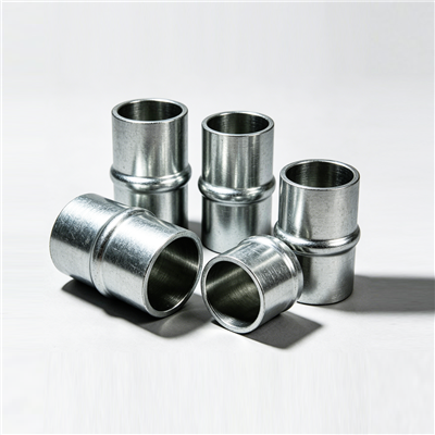
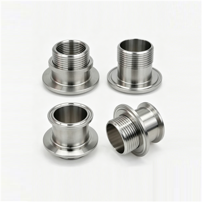
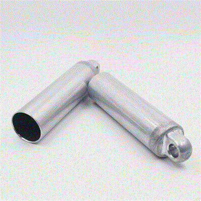
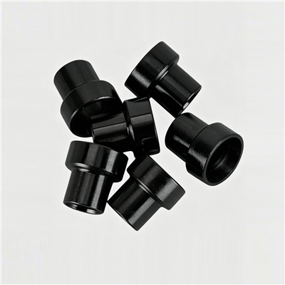
A sleeve, also supplied as a bushing or a tube, is installed inside a hole or on the exterior of a shaft type part. In practice it turns up in three familiar places: connection structures where two components are joined and need a controlled interface, pipe and wire passageways through walls where the sleeve forms the opening, and the bushing positions of moving components where a sliding surface is required. Its duties are simple to state and easy to underestimate. It protects wires, pipes and moving parts from abrasion. It acts as a spacer that positions adjacent components and controls axial or radial clearance. And it withstands radial pressure or provides a low friction surface for another part to run against.
Because a sleeve is usually a low cost turned part inside an expensive assembly, buying it well means understanding which of those three duties is dominant. A protection sleeve and a bearing sleeve look similar on the bench but are specified differently, and the purchasing decision follows from the duty. This guide sets out how to identify the duty, how material and geometry follow from it, and what to put on the drawing or the enquiry.
A protection sleeve lines an opening so that the wire, cable, hose or pipe passing through it does not rub against a sharp edge. The load is modest and mostly abrasion, so the important properties are wall thickness, an internal surface free of burrs, and a generous lead-in radius or chamfer at both ends. Where the passage runs through a metal wall, the sleeve may also be an edge grommet in function, keeping the conductor away from the metal edge for the whole length of the opening.
A spacing sleeve sets the distance between two components on a fastener or a shaft, and controls the axial or radial clearance of the joint. Here the length tolerance and the squareness of the end faces matter more than anything else, because the assembled gap is the sum of the sleeve length and the two faces it sits between. Cutting a tube to length gives a wider length band than turning the part from bar stock, and that difference shows up directly in the assembled clearance.
Where the sleeve is the surface that another part slides or rotates against, it has to carry radial pressure, resist wear and hold its bore dimension in service. The material choice now becomes the central decision, and lubrication, surface finish and the bore clearance window become part of the specification rather than details left to the workshop.
Bonpora supplies sleeves in low carbon steel, stainless steel, copper alloy and aluminium alloy. Each family has a natural duty, and the table below summarises the trade off rather than claiming a universal best choice.
| Material | Typical duty | Trade off to accept |
|---|---|---|
| Low carbon steel | General purpose spacers, protection sleeves in dry locations | Needs a coating to resist corrosion; moderate wear resistance as supplied |
| Stainless steel | Wet, washed down or corrosive locations, visible parts | Higher material cost; can gall against similar stainless parts without a lubricant or a different counterface |
| Copper alloy | Bearing and bushing positions, low friction sliding surfaces | Lower strength than steel; better reserved for moderate radial loads |
| Aluminium alloy | Light weight assemblies, heat conduction, non magnetic applications | Soft, so it wears faster as a bearing surface; needs attention to galvanic pairing |
Two secondary decisions follow from the material. The first is the surface treatment: a zinc or zinc nickel coating on steel, a phosphate finish, anodising on aluminium, or a dry film lubricant where sliding contact is expected. The second is hardness, which matters if the sleeve has to resist wear from a hardened shaft; case hardening or through hardening can be specified for steel sleeves, while non ferrous materials rely on their own bearing characteristics.
The bore is set by the part that passes through or runs inside: wire bundle, pipe outside diameter, bolt shank or shaft. The wall thickness is then a compromise between bearing area and the space available in the housing. Increasing wall thickness raises the radial load the sleeve can carry and reduces the risk of collapse during pressing, but it also reduces the clearance to the surrounding structure. For pressed in sleeves, a wall that is too thin will distort as it is driven home.
For a sleeve pressed into a housing, the outside diameter carries a small interference, typically measured in hundredths of a millimetre on a steel part. The interference is what keeps the sleeve from moving, so it should be specified rather than left to the shop floor. Where the housing is aluminium or a moulded material, a lighter interference is used to avoid cracking the surrounding part.
Length is a functional dimension whenever the sleeve sets a gap, and a wear related one when the sleeve lines a passage. Specify both the overall length and, where relevant, the length of engagement that has to remain in contact with the shaft or pipe. On protection sleeves, an end that ends flush with the panel can leave the conductor in contact with the edge, so allow the sleeve to protrude slightly on both sides.
Chamfer forms are one of the standard customisation options on a sleeve, and they earn their cost at assembly. A lead in chamfer on the outside diameter helps a pressed sleeve start square in the hole. A chamfer or radius on the bore protects a seal, a wire bundle or a shaft as it is introduced. An internal radius also removes the sharp edge that would otherwise cut insulation.
Where a sleeve serves as a bushing, the working clearance is the first thing to fix. Too little clearance and the sleeve will seize as the assembly warms up or as the shaft deflects under load. Too much and the joint becomes noisy, the sleeve wears unevenly and the position of the moving component is no longer controlled. Running clearance is normally specified as a range rather than a single number, so that manufacturing tolerances on both the bore and the shaft stay inside the intended band. Alongside clearance, consider the surface finish of the bore, since a fine turned or reamed finish holds a lubricant film better than a coarse one, and the lubrication route, since a bushing with no way for oil or grease to reach the loaded side will wear on one flank only. In shock absorber and strut work, sleeves of this kind appear at mounting and pivot positions, where they are often replaced together with the rubber element; the mounting bush range covers that side of the assembly.
A passageway sleeve has to do three things at once: protect its contents, survive the panel it passes through and stay in place. Where the panel is thin sheet metal, a flanged sleeve with a shoulder on one side is easier to retain than a plain tube, and the flange also spreads the load from the panel edge. Where the panel is thick or the sleeve is long, a wall thickness large enough to resist crushing during installation is more useful than a tight fit. Where several cables pass through one opening, the sleeve bore should be chosen to give a small clearance around the bundle, because a bore that is too large allows the cables to chafe against one another inside the sleeve.
The table below gives the direction of the fit rather than a drawing replacement, since the correct value depends on the housing material and the duty. Use it to check that a specification is complete.
| Interface | Typical fit intention | Why it matters |
|---|---|---|
| Sleeve outside diameter into steel housing | Light interference, pressed | Prevents rotation and migration of the sleeve in service |
| Sleeve outside diameter into aluminium or plastic housing | Lighter interference or a retained shoulder | Avoids cracking or yielding the softer housing |
| Bore to shaft at a bushing position | Running clearance specified as a range | Controls noise, wear pattern and position of the moving part |
| Bore to wire, cable or pipe | Small clearance, no contact in the fitted state | Prevents abrasion between the contents and the sleeve |
| End faces in a spacing application | Square to the axis within a stated value | The gap in the assembly equals the sleeve length plus the tolerance at both ends |
Sleeves are drawing driven parts. Bonpora supports customisation of different lengths, inner and outer diameters and chamfer forms based on drawings or samples, which means the enquiry should carry the geometry rather than a request for a similar part. The data set that produces a usable quotation is short: inside diameter, outside diameter and length with tolerances, material and any hardness requirement, surface treatment, chamfer or radius details, annual quantity and packing format. Where a sample is the only reference, include a few key dimensions so the factory can confirm the interpretation before cutting metal. Buyers working on a new assembly generally start from a custom parts enquiry, and further machined and formed parts are grouped under metal components. On receipt, the checks below are the ones that catch the problems that would otherwise reach the line.
| Check on receipt | Method | Common defect found |
|---|---|---|
| Bore and outside diameter | Micrometer or plug gauge in two directions at each end | Oval bore, taper from turning, out of tolerance outside diameter |
| Length and squareness | Height gauge or a square against a surface plate | Cut length outside the band, ends not square to the axis |
| Wall thickness | Compare opposite readings, or measure wall directly | Eccentric bore leaving one thin side |
| Chamfer and bore edges | Visual and fingernail check | Sharp internal edge, missing lead in, burr from the cut off operation |
| Surface and coating | Visual, plus a thickness gauge on critical parts | Bare patches, coating missing inside the bore, corrosion bloom |
| Straightness | Roll on a surface plate or check against a straight edge | Bend from handling or from a thin wall after heat treatment |
The three names describe overlapping parts. A tube is a hollow section, usually defined by its outside diameter and wall thickness. A sleeve is a tube used at a specific place in an assembly, either to protect something passing through it or to space two components. A bushing is a sleeve that carries a load from a moving part against its bore, so it is specified for wear and running clearance as well as for size.
Enough to carry the radial load without collapsing, and enough to survive being pressed into the housing without distorting. Protection sleeves through a panel are usually thin, bearing sleeves considerably thicker. As a rule, quote the housing bore, the shaft or bundle that passes through and the expected radial load, and let the factory confirm a workable wall.
It is rarely essential but it is usually worth having. A lead in chamfer on the outside diameter helps the sleeve start square when pressed in, and a radius or chamfer in the bore protects a seal, a shaft or a cable from a sharp edge. Chamfer forms are a standard customisation option, so specify them on the drawing.
Stainless steel is the usual answer for road spray, wash down areas and any sleeve that will be exposed year round, with a coated steel sleeve as the lower cost option where the joint is painted or protected after assembly. Copper alloy is chosen where a low friction bearing surface is the main duty, and aluminium alloy where weight or heat conduction matters more than wear resistance.
Send Bonpora Parts and Components Co.,Ltd. the drawing or the sample together with the inside diameter, outside diameter and length with tolerances, the material, the surface treatment, the chamfer details and the annual quantity. The engineering team will confirm the feasible tolerances and the process route, and can quote single pieces or batch production for assembly line use. The full sleeve, bushing and tube range is listed on the site, and a project can be discussed through contact.