sales@bonporaparts.com
0086-10-64988621
English
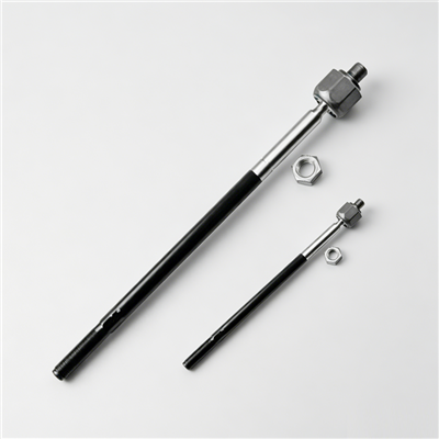
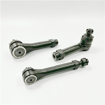
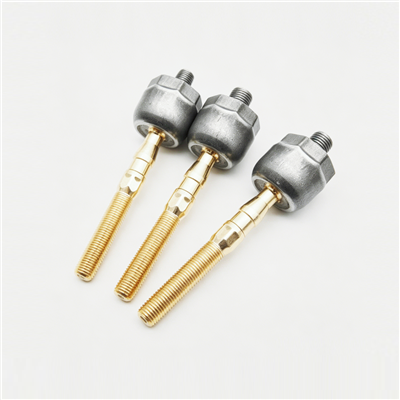
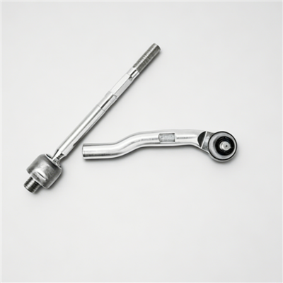
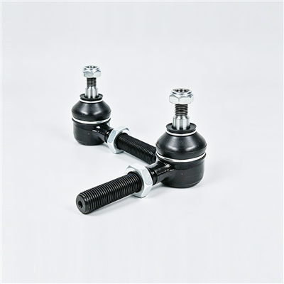
A tie rod, also named steering linkage, track rod, drag link or steering tie rod end, connects the steering gear or steering arm to the steering knuckle arm. It transmits steering torque to turn the wheels and it adjusts the toe angle, because the rod length is set during wheel alignment. The rod body is made of carbon steel or aluminium alloy, and the end ball joint is made of surface hardened alloy steel. Bonpora inspects ball joint torque, axial play, dust cover sealing and overall tensile strength, and gives a one year or 30,000 km quality guarantee for ball joint wear or looseness.
Because the part both steers the vehicle and sets its toe, the fitting procedure carries two separate risks. A joint that is not fully seated changes the steering feel and destroys the taper, and a rod that is not measured before removal leaves the vehicle with an unknown toe setting. The steps below are arranged to remove both risks.
Tie rods are supplied in two commercial forms, and the fitting procedure differs slightly between them. Confirm which one the vehicle needs before the wheels come off.
| Form | How to recognise it | Fitting note |
|---|---|---|
| OE replacement rod | Fixed length matched to an original reference number | Length is set by the part; adjust only for the platform tolerance |
| Adjustable aftermarket rod | Threaded sleeve or threaded rod end for length change | Measure the old rod and transfer the length before fitting |
| Inner tie rod end | Threads into the steering gear or rack | Needs the rack boot to be released and regreased |
| Outer tie rod end | Tapered stud into the knuckle arm | Needs a puller and a check of the taper seat |
The source data states that tie rods can be customised in different lengths, end connection threads and ball joint sizes, and are available as OE replacement or as adjustable aftermarket rods for modification. That flexibility is useful, but it also means the order must state the thread form, the thread hand and the ball joint size explicitly. A right hand thread fitted where a left hand thread is needed will not adjust in the correct direction, and the mistake is usually found only when the alignment operator tries to set the toe.
Record the vehicle identification, the reference number on the removed part and the measured centre to centre length. Where the vehicle has been modified or has an adjustable rod already fitted, measure rather than assume, so that the new part starts from the geometry the vehicle had before the work.
Steering work is done on a supported vehicle with the wheels able to turn freely, so the support method is part of the procedure rather than an afterthought.
Raise the vehicle so that the front wheels are just clear of the ground and place stands under the recommended points, then confirm the steering wheel is free to rotate. Do not work under a vehicle supported only by a jack, and do not turn the steering while a hand is between the tyre and the inner arch.
Many vehicles store a steering angle value that is used by the stability system. If the steering wheel is rotated with the rod disconnected, the stored centre position can move and a warning lamp may appear after the repair. Keep the steering wheel near its straight ahead position while the rods are off the vehicle, and complete a sensor reset if the manufacturer procedure requires one after alignment.
Having the right small items ready is what keeps the job to a single visit. The list below covers most passenger car and light commercial applications.
| Item | Purpose |
|---|---|
| Ball joint separator or pitman arm puller | Releases the tapered stud without shock loading the joint |
| Torque wrench | Sets the ball stud nut and the jam nut to the specified value |
| Steering rack boot clamp pliers | Refits the boot on an inner rod end without damage |
| Thread gauge or caliper | Confirms the thread form and the length before fitting |
| New ball stud nuts and jam nuts | Locking fasteners should not be reused where the specification calls for renewal |
| Grease and a rack boot kit | Restores the sealing at an inner joint |
| Paint marker | Marks the sleeve and the old rod length for transfer |
Add an alignment appointment to the plan. A tie rod replacement changes the toe, and driving a vehicle with an unknown toe setting wears the tyres and can trigger a stability warning, so the alignment should be completed before the vehicle returns to service.
Work one side at a time so the opposite side stays as a reference, and mark every threaded position before loosening anything.
Count and record the exposed thread turns at the adjustment sleeve, and measure the centre to centre distance of the rod. Mark the sleeve and the rod with a paint line so that the count can be confirmed later. On an adjustable rod, this record is the starting point for the new setting.
Remove the nut, then release the taper with a puller. Hammering the knuckle arm or the joint housing to break the taper risks deforming the arm and damaging the new part before it is fitted. Where a puller cannot reach, use the correct separator wedge, and never heat the arm or the stud. Once the stud is free, support the knuckle so the brake hose is not stretched.
Installation is the reverse of removal, with three points that decide whether the repair lasts.
Clean the taper seat in the knuckle arm and check it for damage. Fit the new rod, then pull the taper into the seat by hand and confirm it is fully engaged before fitting the nut, because a taper that is only part way in will still accept a nut and will loosen in service. Check that the thread engagement at the sleeve or the rack end meets the specified minimum, and set the length to the recorded dimension.
Tighten the ball stud nut and the jam nuts to the values in the vehicle specification, and check the thread that locks the sleeve. Locking methods vary: some rods use a jam nut on each side, and some use a clamp bolt or a crimped sleeve. Confirm the method on the rod you have fitted rather than assuming it matches the old part, and recheck the locking after the alignment operator has finished adjusting the length.
The vehicle needs a full alignment after the replacement, not only a check. Setting the toe corrects the effect of the new rod length, and it is also the point where a mis-specified part shows itself: if the adjuster runs out of travel before the toe reaches specification, the rod length or the thread hand is wrong and the part must be exchanged rather than forced.
Watch for an adjuster that has to sit hard against one end of its sleeve, a sleeve that cannot be turned in both directions, and a toe reading that moves in the wrong direction as the sleeve is turned. Any of those three points at a part or a reference mismatch. Record the final toe values and the steering wheel position on the job sheet.
Before handover, run a short list of checks that covers the joint, the sealing and the auxiliary systems.
| Check | Acceptance |
|---|---|
| Ball stud nut torque | At the specified value, with a new nut where required |
| Jam nut and sleeve locking | Both sides tight, no movement when the rod is twisted by hand |
| Dust cover condition | Seated square, no twist, no trapped fold, grease retained |
| Rack boot and clamp | Correctly seated on an inner rod end, no grease loss |
| Toe and steering wheel position | Within specification with the wheel straight ahead |
| Warning lamps | No stability or steering lamp after a short road test |
Most early failures on a new tie rod can be traced to the fitting rather than to the part. The following list covers the recurring cases.
| Error | What happens later |
|---|---|
| Nut tightened with the taper not seated | Looseness and abnormal noise within a short distance |
| Hammer used to break the taper | Deformed knuckle arm or a damaged new joint |
| Dust cover twisted on assembly | Water ingress, grease loss and rapid wear of the surface hardened stud |
| Sleeve locking not rechecked after alignment | Toe drifts out of specification, uneven tyre wear |
| No alignment after replacement | Tyres scrub on one edge and steering pulls to one side |
| Old locking fasteners reused where renewal is specified | Loss of preload and a joint that loosens in service |
Yes. The tie rod sets the toe angle and the rod length is adjusted during wheel alignment, so any replacement changes the setting. Complete the alignment and record the final values before the vehicle returns to service.
An outer end can usually be replaced without opening the boot, while an inner end threads into the steering gear and normally needs the boot released and regreased. Where the boot has to be moved, fit a new clamp and confirm the seal on reassembly.
Record the thread form, the thread hand and the ball joint size from the removed part, and confirm them on the order. Bonpora offers customisation in lengths, end connection threads and ball joint sizes, so stating all three values prevents a return.
List the ball stud nut torque, the jam nut or sleeve locking, the dust cover condition, the rack boot seal where disturbed, the final toe values and the steering wheel position. Add a note of any stability system reset that was carried out.
Use the tie rod range to match the vehicle and confirm the thread form, then compare the joint values in the tie rod specification outline with the part being removed. The failure analysis guide helps decide whether a knock comes from the rod or from a neighbouring joint, and the wholesale sourcing guide covers reference planning for a workshop or distribution stock. Tie rod ends work with the link and ball joint assembly and the control arm range, and adjustable rods for modified vehicles are handled through custom parts. Send the vehicle list through the contact page for a reference proposal.