sales@bonporaparts.com
0086-10-64988621
English
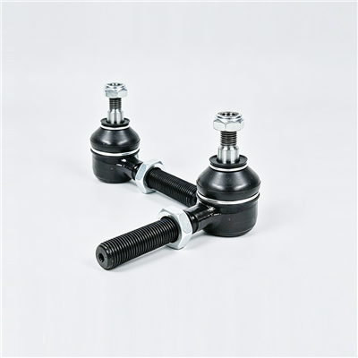
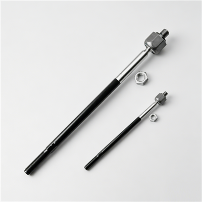
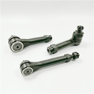
A tie rod, also named steering linkage, track rod, drag link or steering tie rod end, connects the steering gear or the steering arm to the steering knuckle arm. It transmits the steering torque that turns the wheels, and its length is adjusted during wheel alignment to set the toe angle.
The rod body is made of carbon steel or aluminium alloy, and the end ball joint is made of alloy steel with a surface hardened working surface. Quality control covers ball joint torque, axial play, dust cover sealing and overall tensile strength, and the normal guarantee covers ball joint wear or looseness for one year or 30,000 km. This guide sets out how the part is specified and what to confirm before ordering.
The steering gear converts rotational input from the driver into lateral movement, and the tie rod carries that movement out to the wheel. Because it sits between a rotating gear and a wheel that must both steer and travel over bumps, the tie rod has to do two jobs at once. It has to transmit the steering load without deflection or lost motion, and it has to allow the articulation that occurs as the suspension moves through its travel.
That combination is why the part is built as a rod with a ball joint at one or both ends. A rigid link would bind as the suspension moved, and a flexible one would lose steering precision. The ball joint is the component that carries the compromise, so it is the part that wears first and the part that the warranty terms address.
Different manufacturers and markets use these names in overlapping ways, and buyers who shop on a name alone often receive the wrong component.
| Term | What It Normally Refers To |
|---|---|
| Tie rod | The assembly connecting the steering gear or rack to the wheel end |
| Track rod | Common alternative name for the same part on a rack and pinion system |
| Drag link | On a recirculating ball system, the link from the steering box to the steering arm |
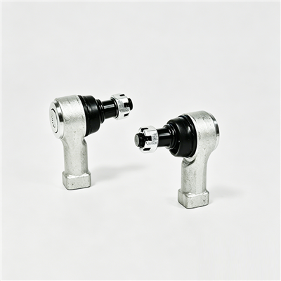
| Tie rod end | The ball joint and threaded shank that screws into the rod or the rack |
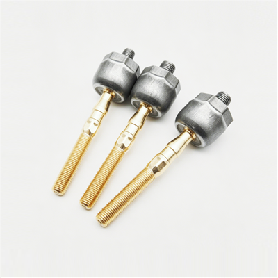
| Inner tie rod end | The joint at the rack or relay end, usually protected by a bellows |
| Outer tie rod end | The joint at the steering knuckle end, with a taper stud and nut |
| Centre link | An intermediate link on some linkage systems, sometimes called a relay rod |
For purchasing, the useful distinction is not the name but the position and the connection. Recording whether the reference is an inner or an outer end, and the thread and taper details of each connection, removes most of the ambiguity.
| Type | Construction | Typical Application |
|---|---|---|
| One piece tie rod assembly | A rod with a fixed joint at one end and an adjustable end at the other | Common on rack and pinion steering |
| Adjustable tie rod | Both ends threaded, adjusted by rotation with a lock nut or clamp | Where toe is set on the vehicle |
| Inner tie rod end | A threaded joint with a ball socket, often with a bellows | Connects to the rack or the steering relay |
| Outer tie rod end | A ball stud with a taper and a socket housing | Connects to the steering knuckle arm |
| Drag link | A link with joints at both ends | Recirculating ball steering systems |
| Adjustable aftermarket rod | Threaded with an extended adjustment range | Modified vehicles and lifted suspensions |
Where the same vehicle is produced with more than one steering system, an assembly that looks similar may not interchange. The connection type at each end is the deciding factor rather than the overall length.
The rod body is normally carbon steel, chosen for stiffness and tensile strength at low cost, or aluminium alloy where weight reduction matters. On a steel rod the surface is usually coated to resist road salt, and the coating is worth specifying because the part is exposed to spray from the front wheel for its whole life.
The ball stud and the socket housing are made of alloy steel with a surface hardened working surface, which gives a hard wear resistant contact while keeping a tough core. The socket contains the bearing material, normally a polymer seat, and is sealed by a dust cover. Grease retention and dirt exclusion are what decide the life of the joint, so the dust cover is as important as the steel specification.
| Element | Function | Failure Effect |
|---|---|---|
| Ball stud, surface hardened | Carries steering load and allows articulation | Wear produces play and steering vagueness |
| Polymer socket seat | Provides a low friction bearing surface | Wear or ovality allows axial play |
| Dust cover | Keeps grease in and grit out | A split cover leads to rapid joint failure |
| Taper stud and nut | Clamps the joint into the knuckle arm | Loosening produces a knock and lost steering feel |
| Lock nut or clamp | Holds the adjustment after alignment | Slack adjustment changes the toe angle in service |
| Bellows at the rack end | Protects the inner joint | A split bellows lets water into the rack |
| Specification | Typical Basis | Why It Matters |
|---|---|---|
| Overall length and centre to centre distance | Steering geometry and the alignment range | Sets the toe adjustment window |
| End connection threads | Thread size, pitch and handedness | Determines whether the part screws into the rack or the end |
| Taper angle and stud diameter | Knuckle arm bore | Controls the clamping fit at the knuckle |
| Rod body material and diameter | Steering load case | Sets stiffness and tensile strength |
| Ball joint torque and axial play limit | Assembly specification | The main acceptance criteria in service |
| Dust cover material and retention | Environmental exposure | Decides joint life in wet and gritty conditions |
| Surface treatment | Finish with a salt spray requirement | Resists corrosion on an exposed part |
| Adjustment range | Standard or extended for modified vehicles | Determines whether the alignment can be achieved |
| Marking | Part number and batch code | Supports identification and traceability |
The two features most often missing from a drawing are the ball joint torque and the dust cover retention method. Without them, the part can be dimensionally correct and still produce a steering complaint within a short distance.
The tie rod is the component that sets the toe angle, and alignment is what makes the adjustment possible. The rod is threaded, and rotating it changes the effective length and therefore the angle of the wheel.
A rod that has reached the end of its adjustment range indicates a bent component, a damaged rack or a suspension geometry change rather than a worn rod end, and replacing the rod alone will not restore the alignment.
| Choice | Advantage | Where It Fits |
|---|---|---|
| OE replacement | Correct length, thread and taper with no adjustment work | Standard repair on an unmodified vehicle |
| Adjustable aftermarket | Extended range for a changed ride height | Lifted or lowered suspensions and competition use |
| Heavy duty rod | Larger stud and stronger body for high load | Commercial vehicles and off road use |
| Service kit | Rod, ends, bellows and lock nuts in one reference | Where the whole assembly is being renewed |
Where a vehicle has been lifted, the standard rod may not have enough adjustment to bring the toe back into specification, and an extended range adjustable rod is the correct solution rather than forcing the alignment with the original part. Customization of different lengths, end connection threads and ball joint sizes is available, which is what allows a specific geometry to be matched rather than approximated.
| Symptom | Likely Cause | Suggested Action |
|---|---|---|
| Steering vague or a dead spot at centre | Axial play in the ball joint | Check the joint with the wheel lifted and rocked |
| Knock over bumps or on turning | Worn joint or a loose taper stud | Check the nut torque and the joint play |
| Uneven or feathered tyre wear | Toe angle outside specification | Check the alignment and the adjustment lock |
| Vehicle wanders at speed | Excessive play across the linkage | Inspect every joint in the system, not only one |
| Grease visible around the joint | Split or displaced dust cover | Replace the end and inspect the bellows |
| Steering wheel off centre | Unequal adjustment between the two sides | Re balance the adjustment and re align |
| Toe will not come into specification | Bent rod or a geometry change | Check the rod for straightness and the ride height |
A worn joint is normally confirmed by axial play rather than by rotational looseness, because a ball joint is designed to rotate freely. Pressing the joint axially while the wheel is lifted is the check that separates normal freedom of movement from wear.
Quality control for this family covers four specific items, and each one addresses a failure mode that a customer would otherwise experience in service.
| Inspection Item | Failure Mode Addressed |
|---|---|
| Ball joint torque | Excessive rotational stiffness or a loose joint |
| Axial play | Steering vagueness and a knock at the joint |
| Dust cover sealing | Grease loss and grit ingress |
| Overall tensile strength | Rod or thread failure under steering load |
The standard quality guarantee covers ball joint wear or looseness, and the declared period is one year or 30,000 km. A buyer dealing with a safety related steering position should ask for the inspection results for the production batch, because a joint that is outside its torque or axial play limit may still pass a simple visual check at goods receiving.
Customisation of different lengths, end connection threads and ball joint sizes is supported from drawings or samples, and both OE replacement and adjustable aftermarket versions are available for modification work.
It depends where the worn joint sits. The inner end connects to the rack or the steering relay and is usually protected by a bellows. The outer end connects to the steering knuckle arm and carries a taper stud with a nut. Where the whole assembly is being renewed, both ends and the rod are normally supplied together as a kit.
The toe angle is set by the length of the rod, so any replacement that disturbs that length changes the alignment. Even where the new rod is set to the same measured length as the old one, a check on an alignment rig is the only way to confirm the toe is within specification, and it is what protects the tyres and the steering feel.
The standard guarantee covers ball joint wear or looseness for one year or 30,000 km. It does not normally cover damage caused by a split dust cover that has been left in place, or by a joint that has been run with the taper stud loose in the knuckle arm, because those are conditions outside the design assumptions of the part.
Where the ride height has been changed by lifting or lowering, the standard rod may not have enough range to bring the toe angle back into specification. An adjustable rod with an extended range allows the geometry to be corrected properly rather than forcing the alignment with a part that has reached the end of its adjustment. Related front end parts are described on the suspension bushing and chassis and suspension pages.
Bonpora Parts supplies tie rods, track rods, drag links and tie rod ends with carbon steel or aluminium alloy rod bodies and surface hardened alloy steel ball joints, inspected for ball joint torque, axial play, dust cover sealing and overall tensile strength, and covered by a one year or 30,000 km guarantee against ball joint wear or looseness. Both OE replacement and adjustable aftermarket versions are available, and customisation of different lengths, end connection threads and ball joint sizes is quoted from drawings or samples. Start from the tie rod range, review the matching dust covers, spring seats and shock absorber parts supplied on the same route, or contact our team with your specification and annual volume. New dimensions are quoted under custom moulded and bonded parts, and further references are listed on the products page.