sales@bonporaparts.com
0086-10-64988621
English
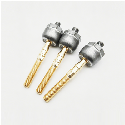
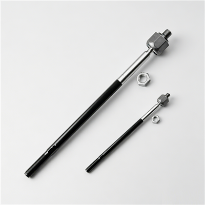
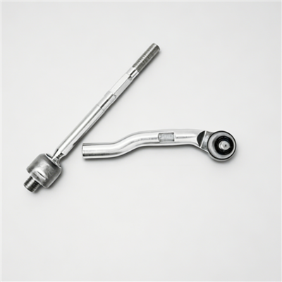
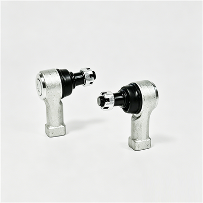
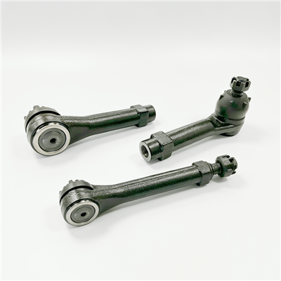
A tie rod, also named steering linkage, track rod, drag link or steering tie rod end, connects the steering gear or steering arm to the steering knuckle arm. It transmits steering torque so the wheels turn, and it adjusts toe angle because the rod length is set during wheel alignment. The rod body is made of carbon steel or aluminium alloy, and the end ball joint is made of surface hardened alloy steel. Bonpora inspects ball joint torque, axial play, dust cover sealing and overall tensile strength, and warrants the part for one year or 30,000 km against ball joint wear or looseness.
Those four inspection items are the manufacturing brief. Ball joint torque and axial play come from the pressing and staking step combined with the spherical finish of the stud. Dust cover sealing comes from the cover compound and the way it is seated. Tensile strength comes from the rod body route, the thread form and the weld or joint that connects the ball end to the rod. A buyer who knows which step sets each value can audit a supplier in an hour and read a control plan with confidence.
The source data allows carbon steel or aluminium alloy for the rod body. The route chosen for that body decides the achievable strength, the weight and the corrosion strategy of the finished rod.
| Route | Starting material | Strength of the route | Watch point |
|---|---|---|---|
| Tube drawing with swaged or welded ends | Welded or seamless steel tube | Light weight at high bending stiffness, suited to volume | Weld seam position and end form cracking |
| Solid bar turning and threading | Carbon steel bar | Simple tooling, easy to adjust length in small batches | Higher weight, thread concentricity |
| Aluminium extrusion or forging | Aluminium billet | Low mass, good for performance and aftermarket rods | Galvanic isolation at steel interfaces, thread pull-out strength |
Where the rod has swaged or welded ends, the transition zone is the part that carries the bending moment. The swage needs a controlled reduction per pass, and a welded end needs a qualified procedure with the filler material recorded. Concentricity matters as well, because a thread that is not coaxial with the rod axis will bind in the adjuster sleeve and will not hold the toe setting under load.
A tie rod that is not straight transmits a side load into the joint and into the rack. Straightness is normally checked on a bench with a dial indicator or a straightness gauge, and the acceptance value belongs on the drawing. Ask for the check to be carried out after the coating step, because some coating processes introduce a small distortion.
The adjustment feature is what distinguishes a steering tie rod from a plain link. Its form varies between models, so production has to be organised around the specific design.
Rolled threads are formed by displacing material rather than removing it, which leaves a favourable compressive stress at the thread root and usually gives a stronger joint at the same diameter. Cut threads are simpler to produce on a lathe and are common on small batches and on solid bar rods. When comparing two offers for the same reference, ask which method is used, because the difference shows up in the tensile result rather than in the appearance.
Locking is achieved by a jam nut on each side of the sleeve, by a clamp bolt on a split sleeve, or by a crimped feature. Each method needs its own control: the jam nut needs a thread gauge and a torque value, the clamp needs a defined gap after tightening, and the crimp needs a depth and width check. A rod whose locking feature is out of specification will hold toe during alignment and then drift in service, which is a common source of an unsatisfactory repair that is blamed on the workshop.
The stud is described in the source data as alloy steel with a surface hardened condition. Surface hardening is the key word: the stud has to resist fretting and wear at the spherical surface while keeping a tough core, so that the taper and the thread do not become brittle.
Induction hardening or case carburising both produce a hard surface over a softer core. The parameters to record are the surface hardness, the effective case or hardened depth, and the core hardness after tempering. A depth that is too shallow wears through quickly, and one that is too deep leaves insufficient tough material under the taper. Check that the hardness value is quoted with the test location and the method, not as a single number.
The spherical face is ground or burnished to a controlled surface roughness after hardening, because the finish sets the friction level that the ball joint torque value depends on. Roughness should be a drawing specification with a measuring instrument named, and the finish should be re-checked after any subsequent coating step that touches that face. A stud that is polished to a mirror finish can be as problematic as a rough one, because the torque band becomes too wide to control.
The joint is completed when the stud, the bearing element and the housing are brought together and the cover is seated. This is where axial play and dust cover sealing are decided.
Presses used for joint assembly should be monitored on both force and displacement. Controlling only one of the two cannot separate a variation in the polymer bearing element from a variation in the housing height. The force-versus-displacement curve per part gives the setting value and a trace for the batch record at the same time, which is useful if a warranty claim ever needs a production record.
The correct quantity of the correct grease is a specification, not a preference. Under-filling leaves the bearing surface dry and over-filling can stress the cover as the joint moves. Seat the cover with a tool that supports the full circumference, then confirm that the retention ring is fully engaged by a visual check and a light pull test on a sample. A cover fitted with a twist fails early even when the compound is correct, and the source data confirms that the cover material can be customised for a demanding climate.
Bonpora states that ball joint torque, axial play, dust cover sealing and overall tensile strength are inspected. A well-built line names the method, the gauge and the frequency of each rather than treating them as a final gate.
| Inspection item | Method to look for | Frequency |
|---|---|---|
| Ball joint torque | Torque gauge on a fixed fixture at a stated swing angle or rotation count | Every part at the station, plus a sample record per shift |
| Axial play | Dial indicator under a stated axial load | Sample per shift, and at the end of the durability run |
| Dust cover sealing | Visual seating check plus a seal or water ingress test on a sample | Every part visually, sample test per compound batch |
| Overall tensile strength | Pull test to a stated load on a sample rod assembly | Per production lot, and on the qualification sample |
Ask for the calibration interval of the torque gauge and the pull test frame as well, since a reading is only as trustworthy as the equipment behind it. An uncalibrated fixture can pass a joint that is already loose or fail a good one, and both outcomes cost the buyer money.
Each production route has its own characteristic defects. The table below lists the common cases in this product family and the process step that normally causes them.
| Found at inspection | Likely process cause | Correction |
|---|---|---|
| Ball joint torque below the band | Stake depth shallow, bearing element undersized | Re-set the press window, verify the component lot |
| Axial play over the limit | Housing height variation after forming or moulding | Review tooling dimensions and cooling or relaxation time |
| Tensile result below the drawing value | Thread form, weld quality or swage reduction outside limits | Re-qualify the thread method or the welding procedure |
| Cover twisted or leaking | Seating tool worn or wrong compound for the specification | Replace the tool, verify the compound lot |
| Thread binds in the sleeve | Thread concentricity or coating build-up | Check the threading setup, mask the thread during coating |
| Surface rust on the stud taper | Coating skip, damaged packing | Review the coating jig and the inner packaging |
A tie rod lives under the vehicle and is exposed to spray, so the coating system is a functional specification rather than a finish detail. The choice also has to respect the thread and the taper, because added thickness on either face changes the fit.
| Coating option | Typical benefit | Point to confirm |
|---|---|---|
| Zinc plating with passivation | Low cost, good general protection | Hydrogen embrittlement relief on hardened parts |
| Zinc flake | Good salt spray performance, thin film | Thread and taper masking to avoid interference |
| Cataphoretic dip coating | Uniform coverage including hidden areas | No coating on the spherical bearing face |
| Anodising for aluminium rods | Corrosion protection without added mass | Isolation washers at steel interfaces to limit galvanic attack |
Whatever the system, confirm how the thread and the tapered seat are protected during the coating step and whether the spherical surface is masked. A coating that reaches the spherical face will change the ball joint torque and can make the joint feel tight when new and loose after a short period of use.
Ask how a delivered rod can be traced to its steel heat, its hardening batch, its press record and its cover compound lot. A date code on the rod or the bag, plus a packing list that carries the lot number, is normally enough, provided the records are retained for the length of the warranty period. With one year or 30,000 km of cover, the practical requirement is that the record survives at least that long and that the marking stays legible after the part is fitted.
Shipping protection closes the loop. A surface hardened stud with a machined taper will show surface rust after a humid sea voyage if the coating and the inner packing are not specified, and rust on a machined face is a frequent reason for a rejected consignment. Confirm the individual protection and any desiccant or barrier layer, and compare one carton at goods-in against the sample that was approved.
Surface hardening gives a wear resistant spherical face while the core stays tough, so the taper and the thread resist impact without becoming brittle. The recorded values should include the surface hardness, the effective hardened depth and the core hardness, since a depth that is too shallow or too deep both reduce life.
Rolled threads leave a compressive stress at the root and usually give a stronger joint at the same diameter, so they are preferred where tensile strength is a specified value. Cut threads remain common on small batches and on solid bar rods. Ask which method is used when comparing quotations for the same reference.
The cover is checked visually for a square, untwisted seat on every part, and a sample is tested for sealing or water ingress per compound batch. Because Bonpora lists dust cover sealing as an inspected item, the sealing test method and the sample size should appear in the inspection record.
Yes. Bonpora offers customisation in length, end connection threads and ball joint sizes, as OE replacement or as an adjustable aftermarket rod, with batch and small-batch production supported. Tooling cost should be quoted separately from the unit price when a new length or thread is introduced.
Start from the tie rod range to see the references in production, then compare the drawing values with the tie rod specification outline. The installation guide shows which production values the workshop can confirm after fitting, and the failure analysis guide explains how a process deviation appears in service. Commercial terms, lot planning and reference range building are covered in the wholesale sourcing guide. The ball joint side of the assembly is described under link and ball joint, adjustable rods for modified vehicles go through custom parts, and inspection records can be requested through the contact page.